
Special Instructions for Model-Specific VME Hardware
D-2
014–001867
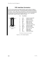
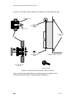
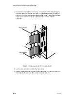
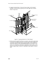
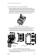
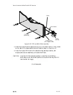
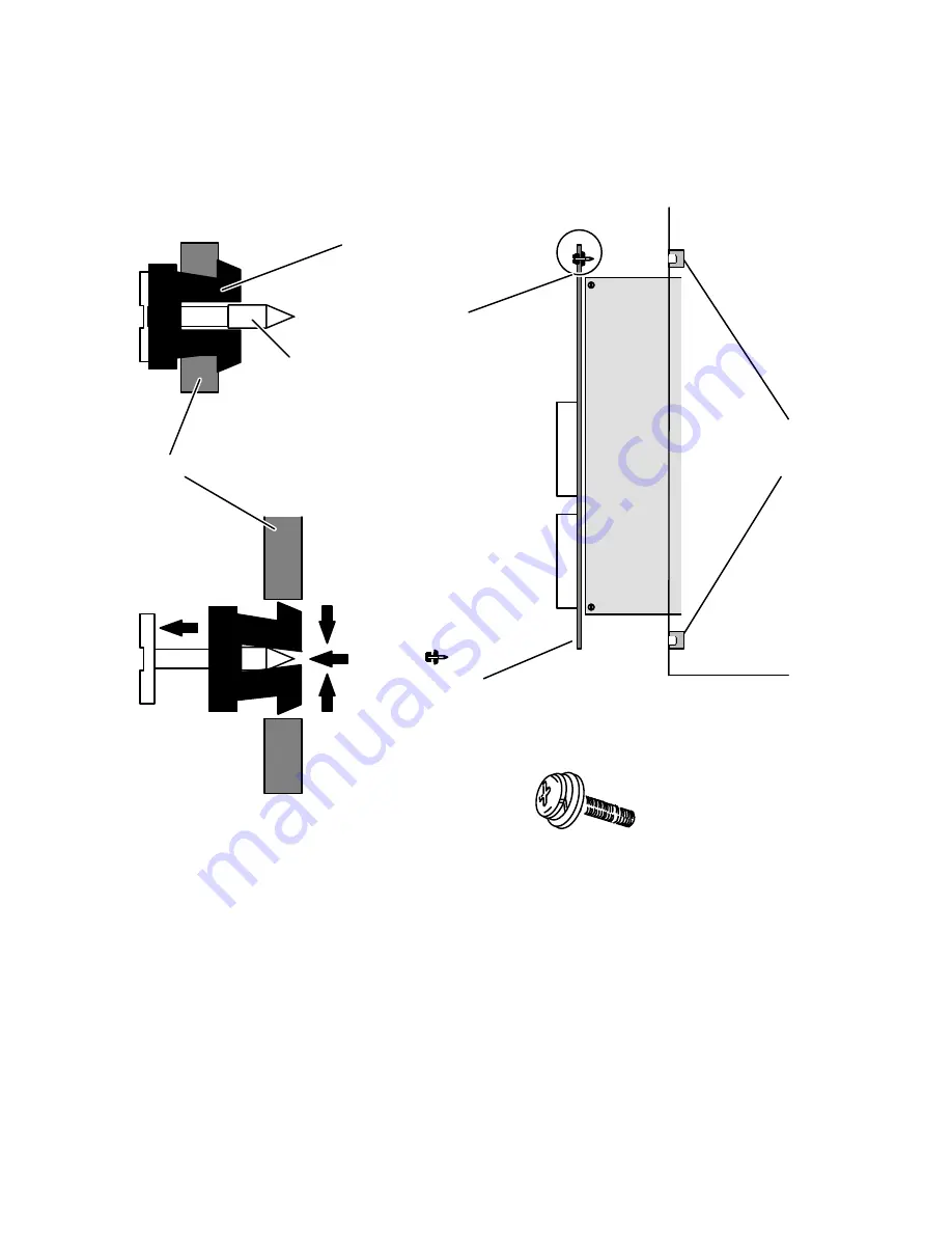
Figure D–1 illustrates how to replace securing screws on an option board air dam.
Securing bars
(internal)
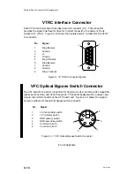
Computer chassis — side view
É
ÉÉÉ
ÉÉÉ
ÉÉÉ
ÉÉÉ
É
Stand-off
and captive screw
installed
Stand-off
and captive screw
removed
Removing stand-off
and screw
Replacement screw
Plastic stand-off
Captive screw
Air dam
Figure D–1 Removing Screws and Stand-offs from Air Dam
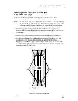
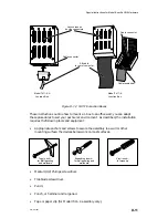
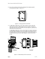
Once you have secured the board(s) in the card cage, return to Chapter 3 and
continue with the last section, “Completing the Configuration.”
Содержание AViiON 5000 Series
Страница 2: ......
Страница 6: ......
Страница 12: ...Preface x 014 001867 ...
Страница 86: ...Configuring VME Option Boards 2 52 014 001867 ...
Страница 144: ...Connecting External Devices to VME Option Boards 4 44 014 001867 ...
Страница 150: ...VME Backplane Connector Signals and Power Distribution A 6 014 001867 ...
Страница 196: ...Assigning VME Data Bus and Interrupt Priorities E 10 014 001867 ...
Страница 206: ......
Страница 209: ...Cut here and insert in binder spine pocket Setting Up and Installing VMEbus Options in AViiON Systems 014 001867 03 ...
Страница 210: ...Appendix Title ...


