VME Backplane Connector Signals and Power Distribution
A-5
014–001867
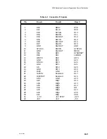
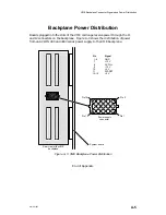
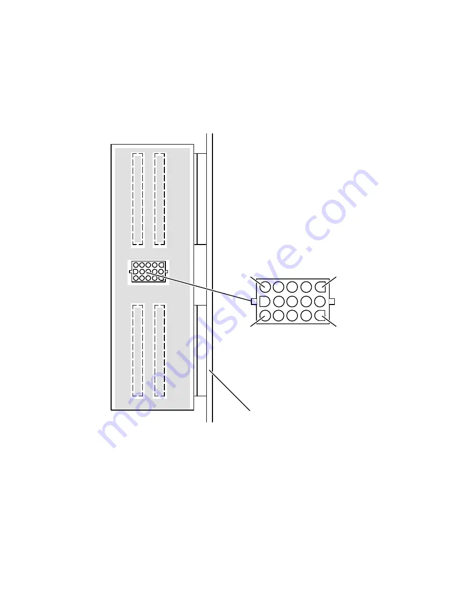
Backplane Power Distribution
Boards plugged into the slots of the VME card cage receive power through the J1
and J2 connectors on the backplane. Figure A–3 shows the distribution of power
from an AViiON 400 and 4000 series power supply to the VME backplane.
Power supply
connector
Pin 3
Pin 1
Pin 15
Rear view of the VME
backplane
ÇÇ
ÇÇ
ÇÇ
ÇÇ
ÇÇ
ÇÇ
ÇÇ
ÇÇ
ÇÇ
ÇÇ
ÇÇ
ÇÇ
ÇÇ
ÇÇ
ÇÇ
ÇÇ
ÇÇ
ÇÇ
ÇÇ
ÇÇ
ÇÇ
ÇÇ
ÇÇ
ÇÇ
ÇÇ
System board
Pin 13
Pin
Signal
1–6
GND
7
+12 V
8
AC FAIL
9
–12 V
10
+5 V
11
SYSRST
12–15
+5 V
Figure A–3 VME Backplane Power Distribution
End of Appendix
Содержание AViiON 5000 Series
Страница 2: ......
Страница 6: ......
Страница 12: ...Preface x 014 001867 ...
Страница 86: ...Configuring VME Option Boards 2 52 014 001867 ...
Страница 144: ...Connecting External Devices to VME Option Boards 4 44 014 001867 ...
Страница 150: ...VME Backplane Connector Signals and Power Distribution A 6 014 001867 ...
Страница 196: ...Assigning VME Data Bus and Interrupt Priorities E 10 014 001867 ...
Страница 206: ......
Страница 209: ...Cut here and insert in binder spine pocket Setting Up and Installing VMEbus Options in AViiON Systems 014 001867 03 ...
Страница 210: ...Appendix Title ...

