background image


Ordercode: D1356 

DM-35


Set Up and Operation 

Follow the directions below, as they pertain to your preferred operation mode. Before plugging the unit 
in, always make sure that the power supply matches the product specification voltage.  


01)


Set all volume and gain controls on your mixer, mic preamp or recording device to the minimum 
before connecting the microphone. Make sure that the phantom power is off! 

02)


Once the DM-35 is plugged in, move the channel fader gradually to the 0dB position. Adjust the 
input gain, using your channel peak LED or the VU-meter. 

03)


Make sure the microphone is aimed towards the speaker with the front side (silver). 

04)


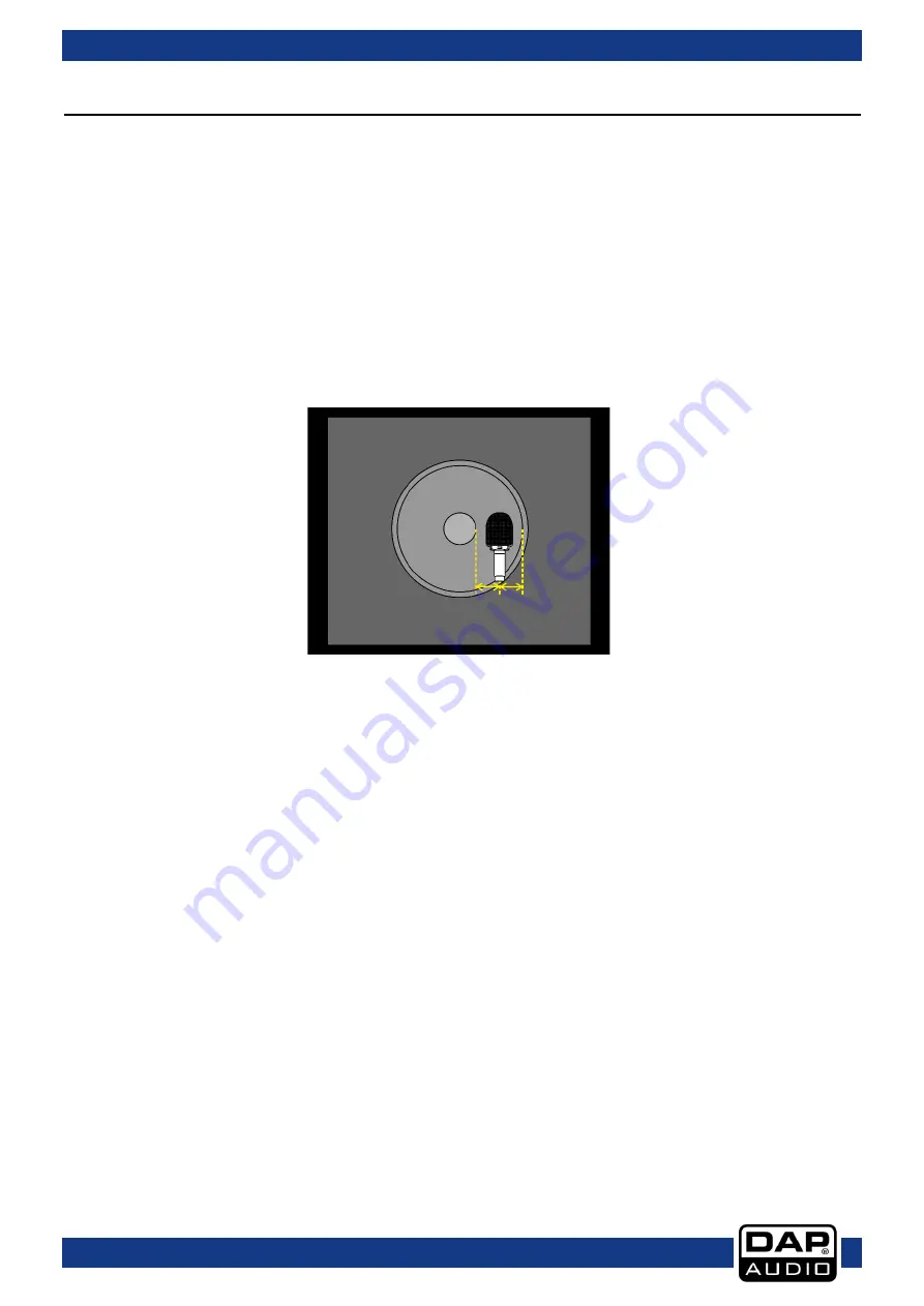
Position the microphone exactly in the middle between the edge of the dust cap and the edge of 
the speaker as shown on Fig. 02, page 6. 

05)


Once positioned, use your ear to find the optimum position. Moving the microphone in the direction 
of the dust cap will increase the brilliance of the signal. Moving the microphone towards the edge of 
the speaker will decrease the brilliance, and the sound will become warmer. 


Setup example 


Fig. 02 


Make sure the front of the microphone (silver side) is facing the speaker. 


Position the microphone exactly in the middle between the edge of the dust cap and the edge of 
the speaker as shown on Fig. 02, page 6. Once positioned use your ear to find the optimum position. 
Moving the microphone in the direction of the dust cap will increase the brilliance of the signal. 
Moving the microphone towards the edge of the speaker will decrease the brilliance, and the sound 
will become warmer. 


Содержание D1356

Страница 1: ...DM 35 V2 Highlite International B V Vestastraat 2 6468 EX Kerkrade the Netherlands Ordercode D1356 MANUAL ENGLISH...

Страница 2: ...ion with the mains 3 Return Procedure 4 Claims 4 Description of the device 5 Overview 5 Installation 5 Set Up and Operation 6 Setup example 6 Frequency and Polar Diagrams 7 Connection Cables 8 Compens...

Страница 3: ...r shipment includes DAP DM 35 Microphone clip Gooseneck clamp Pouch User manual Safety Instructions Every person involved with the installation operation and maintenance of this system has to be quali...

Страница 4: ...ge your system Leave the system switched off until it has reached room temperature Don t put your equipment next to TV radio etc because of interference or distortion If your DAP Audio device fails to...

Страница 5: ...number 04 A brief description of the symptoms Claims The client has the obligation to check the delivered goods immediately upon delivery for any short comings and or visible defects or perform this c...

Страница 6: ...dBV Pa 1 8 mV Maximum SPL 150dB THD 1 1000Hz Impedance 200 Connections 1 x 3 pin XLR OUT Accessories gooseneck clamp mic clip pouch Dimensions microphone 136 x 54 x 46 mm L x W x H Weight 0 2 kg Over...

Страница 7: ...the middle between the edge of the dust cap and the edge of the speaker as shown on Fig 02 page 6 05 Once positioned use your ear to find the optimum position Moving the microphone in the direction o...

Страница 8: ...7 Ordercode D1356 DM 35 Frequency and Polar Diagrams Fig 03 Fig 04...

Страница 9: ...d reliability Periodically check your cables A great number of problems faulty contacts ground hum discharges etc are caused entirely by using unsuitable or faulty cables Unbalanced Balanced Headphone...

Страница 10: ...sure connections are thoroughly dry before linking equipment or supplying electric power Troubleshooting DAP Audio DM 35 This troubleshooting guide is meant to help solve simple problems If a problem...

Страница 11: ...uency response 80 18000Hz Polar pattern Super Cardioid Sensitivity 55 dBV Pa 1 8 mV Maximum SPL 150dB THD 1 1000Hz Impedance 200 Connections 1 x 3 pin XLR OUT Accessories gooseneck clamp mic clip pouc...

Страница 12: ...2018 DAP Audio...

Отзывы: