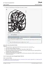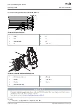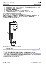
1.
2.
3.
-
a.
-
b.
4.
1.
2.
3.
4.
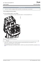
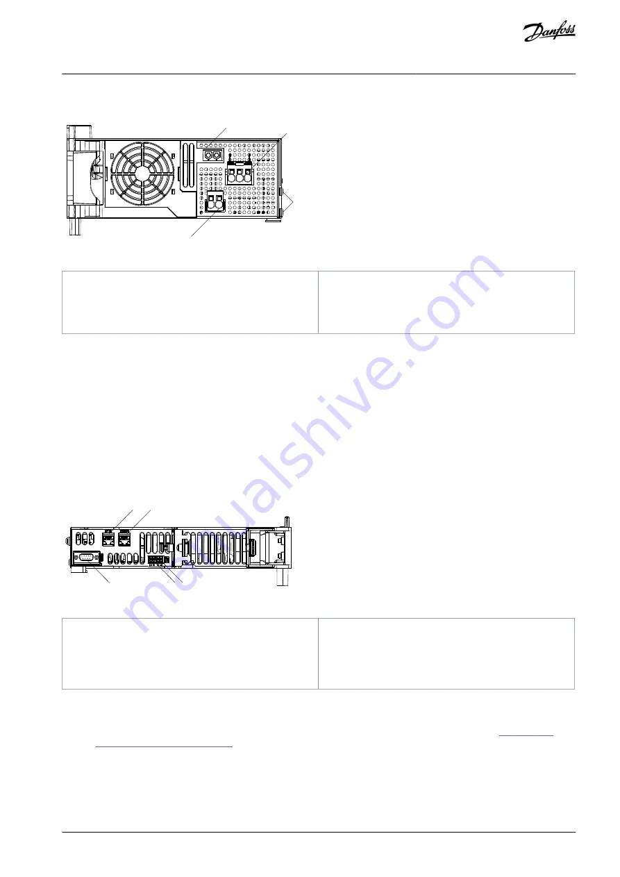
5.9.2.2.2 Connecting the Cables on the Bottom of the Power Supply Module PSM 510
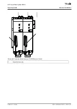
2
1
3
4
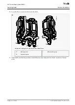
e30bg466.10
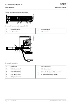
Illustration 30: Connectors on the Bottom of PSM 510
1
Holder for internal brake resistor connector when
not in use
2
AC mains supply connector
3
PE screws
4
Internal/external brake resistor connector
Procedure
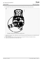
Insert the wires into the AC mains supply connector.
Insert the AC mains supply connector [2].
If an external brake resistor is required:
Unplug the internal brake resistor connector [4] and insert the external brake connector in its place.
Plug the internal brake resistor connector to the internal brake connector holder [1].
Connect the PSM 510 to PE using one of the PE screws on the front side [3] and a PE wire. The tightening torque is 3 Nm.
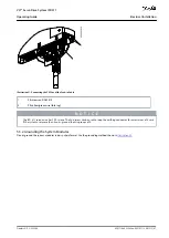
5.9.3 Connecting the Decentral Access Module (DAM 510)
5.9.3.1 Connecting the Cables on the Top of the Decentral Access Module DAM 510
1
2
3
4
5
e30bg467.10
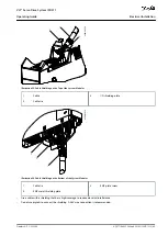
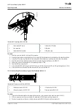
Illustration 31: Connectors on the Top of DAM 510
1
Ethernet connector IN (X1 IN)
2
Ethernet connector OUT (X3 OUT)
3
STO connector IN (STO DAM)
4
STO connector OUT (STO DAM)
5
External encoder connector (E DAM)
Procedure
Connect the Ethernet cable from the output of the previous module to the input connector (X1 IN) [1].
Insert the wires from the STO output of the previous module into the 24 V IN (STO input) connector, see
Connectors on the Top of DAM 510
Insert the 24 V IN (STO connector IN (STO DAM)) connector [3] into the DAM 510.
If required, connect the external encoder connector [5].
AQ377148425069en-000101
/ 130R1213 | 59
Danfoss A/S © 2023.08
Electrical Installation
VLT® Servo Drive System ISD 511
Operating Guide
Содержание VLT ISD 511
Страница 1: ...Operating Guide VLT Servo Drive System ISD 511 drives danfoss com...
Страница 2: ......

