Function
Description
Guide value
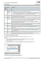
The guide value is used in all synchronous modes of operation (
CAM mode
and
Gear mode
). It is used as the
master position within the synchronous modes.
7.2 Operating Status Indicators
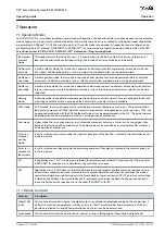
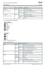
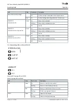
The operating status of the ISD 510/DSD 510 servo drive, PSM 510, DAM 510, and ACM 510 is indicated via the LEDs on each device.
7.2.1 Operating LEDs on the ISD 510/DSD 510 Servo Drive
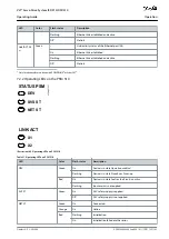
DEV STAT
X1
X2
X3
NET STAT
LINK/ACT
Advanced
e3
0b
e6
77
.1
1
Illustration 104: Operating LEDs on the ISD 510/DSD 510 Servo Drive
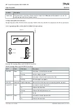
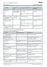
Table 30: Operating LEDs on the ISD 510/DSD 510 Servo Drive
LED
Color
Flash status
Description
DEV STAT
Green
On
Servo drive is in state
Operation enabled
Flashing
Auxiliary voltage is applied.
Red
On
Servo drive is in
Fault
or
Fault reaction active
state.
Flashing
DC-link voltage is not applied.
NET STAT
Green/red
Fieldbus dependent
Network status of the device (see corresponding fieldbus standard).
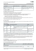
Link/ACT X1
Green
–
Link/activity status of
Hybrid In
(X1)
On
Ethernet link established.
Flashing
Ethernet link established and active.
Off
No link.
Link/ACT X2
Green
–
Link/activity status of
Hybrid Out
(X2)
On
Ethernet link established.
AQ262449648484en-000101 / 175R1135
142 | Danfoss A/S © 2020.08
Operation
VLT® Servo Drive System ISD 510/DSD 510
Operating Guide

