


7.
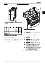
Use the navigation keys to scroll to parameter
group
Q2 Quick Setup
and press [OK].
130BB847.10
Q1 My Personal Menu
Q2 Quick Setup
Q5 Changes Made
Q6 Loggings
13.7% 13.0A 1(1)
Quick Menus
Illustration 3.4
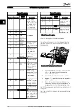
8.
Select language and press [OK]. Then enter the
motor data in parameters 1-20/1-21 through 1-25.
The information can be found on the motor
nameplate.
1-20 Motor Power [kW]
or
1-21 Motor
Power [HP]
1-22 Motor Voltage
1-23 Motor Frequency
1-24 Motor Current
1-25 Motor Nominal Speed
130B
T772.10
Q2
0.0 Hz 0.00kW 1(1)
Motor Setup
1 - 21 Motor Power [kW]
4.0
kW
Illustration 3.5
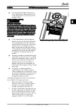
9.
A jumper wire should be in place between
control terminals 12 and 27. If this is the case,
leave
5-12 Terminal 27 Digital Input
at factory
default. Otherwise select
No Operation
. For
frequency converters with an optional Danfoss
bypass, no jumper wire is required.
10.
3-02 Minimum Reference
11.
3-03 Maximum Reference
12.
3-41 Ramp 1 Ramp Up Time
13.
3-42 Ramp 1 Ramp Down Time
14.
3-13 Reference Site
. Linked to Hand/Auto* Local
Remote.
This concludes the quick set-up procedure. Press [Status]
to return to the operational display.
3.4 PM Motor Setup
This section is only relevant when using a PM motor.
Set up the basic motor parameters:
•
1-10 Motor Construction
•
1-14 Damping Gain
•
1-15 Low Speed Filter Time Const.
•
1-16 High Speed Filter Time Const.
•
1-17 Voltage filter time const.
•
1-24 Motor Current
•
1-25 Motor Nominal Speed
•
1-26 Motor Cont. Rated Torque
•
1-30 Stator Resistance (Rs)
•
1-37 d-axis Inductance (Ld)
•
1-39 Motor Poles
•
1-40 Back EMF at 1000 RPM
•
1-66 Min. Current at Low Speed
•
4-13 Motor Speed High Limit [RPM]
•
4-19 Max Output Frequency
Note concerning advanced motor data:
Stator resistance and d-axis inductance values are often
described differently in technical specifications. For
programming resistance and d-axis inductance values in
Danfoss frequency converters, always use line to common
(starpoint) values. This is valid for both asynchronous and
PM motors.
Par.
1-30
Stator
Resistance
(Line to
common)
This parameter gives stator winding
resistance (Rs) similar to asynchronous
motor stator resistance. When line-line
data (where stator resistance is
measured between any two lines) are
available, you need to divide it with 2.
Par.
1-37
d-axis
Inductance
(Line to
common)
This parameter gives direct axis
inductance of the PM motor. When line-
line data are available, you need to
divide it with 2.
Par.
1-40
Back EMF at
1000RPM
RMS (Line to
Line Value )
This parameter gives back EMF across
stator terminal of PM Motor at 1000RPM
mechanical speed specifically. It is
defined between line to line and
expressed in RMS Value. In case the PM
Motor specifications provides this value
related to another motor speed, the
voltage must be recalculated for 1000
RPM.
Table 3.2
Note concerning Back-EMF:
Start Up and Functional Tes...
VLT
®
HVAC Drive Operating Instructions
MG11AH02 - VLT
®
is a registered Danfoss trademark
27
3
3


