


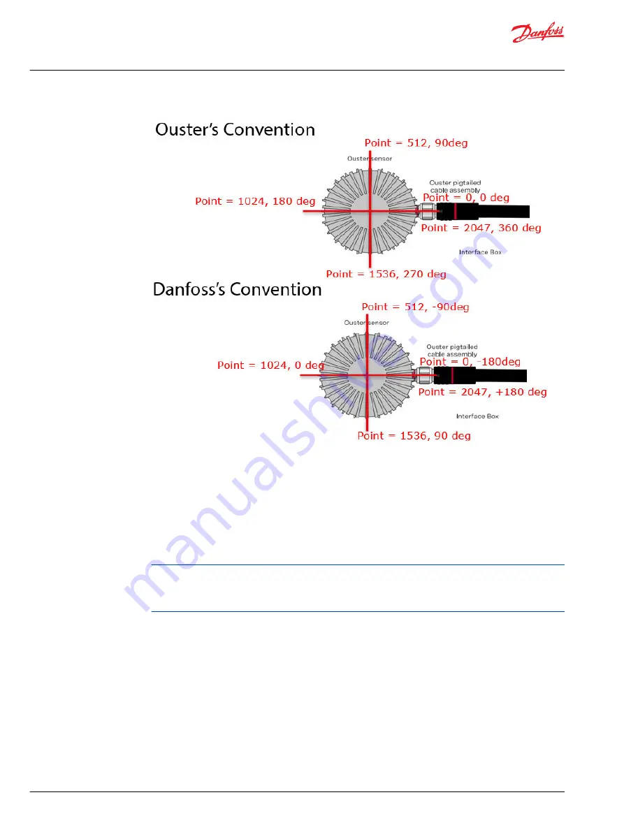
The image shows Danfoss's 180° rotation compared to Ouster's 360° rotation if Ouster LiDAR hardware
horizontal resolution scans 2048 points per rotation (starting at point 0 and ending at point 2047). In that
instance, data point 512 is at the exact spot of angle -90° using Danfoss's coordinate system but at angle
90° in Ouster's system.
Examples:
•
Forward: Set Min_Azimuth_Bound to -9000 (-90°) and set Max_Azimuth_Bound to 9000 (90°).
•
To the left: Set Min_Azimuth_Bound to 0 (0°) and set Max_Azimuth_Bound to 18000 (180°).
•
To the right: Set Min_Azimuth_Bound to -18000 (-180°) and set Max_Azimuth_Bound to 0 (0°).
At this time, the Ouster LiDAR compliance block does not support pointing the azimuth window
backwards towards the connector or any other azimuth window that requires the Min_Azimuth_Bound
to be greater than the Max_Azimuth_Bound. To meet this requirement, mount the Ouster LiDAR
hardware to point backward in relation to the orientation of the vehicle.
Rings
Ouster LiDAR hardware comes in several different channel options.
Danfoss software specifies ring row zero starts at the top of the LiDAR sensor, even though some types of
Ouster LiDAR hardware have ring row zero starting at the bottom of the LiDAR. The first row starts at Row
0 rather than Row 1, so the row at the bottom is the channel number with one number subtracted.
Depending on the Ouster LiDAR hardware, ring rows in the center project data points closer together
than ring rows on the top and bottom. This limits the LiDAR's ability to determine the height of objects.
User Manual
Ouster LiDAR
Introduction
12 |
©
Danfoss | March 2023
AQ404281942428en-000103


