
FCC rules
This equipment has been tested and found to comply with the limits for a Class A digital device, pursuant
to Part 15 of the FCC Rules.
Changes or modifications not expressly approved by the manufacturer can void the user's authority to
operate the equipment.
To comply with FCC RF exposure compliance requirements, this device and its antenna must not be
collocated with, or operating in conjunction with, any other antenna or transmitter, may not cause
harmful interference, and must accept any interference received, including interference that may cause
undesired operation.
The limits are designed to provide reasonable protection against harmful interference when the
equipment is operated in a commercial environment. This equipment generates, uses, and can radiate
radio frequency energy, and if not installed and used in accordance with the instruction manual, may
cause harmful interference to radio communications.
Operation of this equipment in a residential area is likely to cause harmful interference in which case the
user will be required to correct the interference at his own expense.
W
Warning
Le présent appareil est conforme aux CNR d'Industrie Canada applicables aux appareils radio exempts de
licence. L'exploitation est autorisée aux deux conditions suivantes:
1. l'appareil ne doit pas produire de brouillage, et
2. l'utilisateur de l'appareil doit accepter tout brouillage radioélectrique subi, même si le brouillage est
susceptible d'en compromettre le fonctionnement.
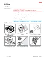
MP08A General Safety
The following safety instructions must be read carefully to install and use the product properly, and to
keep it in perfect working condition, and to reduce the risk of misuse.
•
Strictly adhere to the installation instructions contained in this document.
•
Make sure that professional and competent personnel carry out the installation.
•
Ensure that all site and prevailing safety regulations are fully respected.
•
Make sure that this document is permanently available to the operator and maintenance personnel.
•
Keep the transmitter out of reach of non-authorized personnel.
•
Remove the transmission key when the set is not in use.
•
Check each working day the STOP button and other safety measures. When in doubt, press the STOP
button.
•
Whenever several sets have been installed, make sure the transmitter is the right one. Identify the
machine controlled on the label for this purpose on the transmitter or by using the display (in case it
has one).
•
Service the equipment periodically.
•
When carrying out repairs, use spare parts supplied by Danfoss only.
W
Warning
Potential damage to the operator or the product. Do not use this product on machines in potentially
explosive atmospheres unless the model is ATEX/RATEX certified to work in such conditions.
User Manual
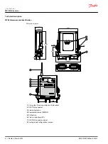
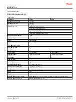
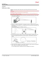
MP08A Receiver
Safety instructions
4 |
©
Danfoss | March 2022
BC292475492602en-000201


