


Preliminary Conditions
The following set-up procedure should be performed after hydraulic nulling of the servovalve has taken
place. These steps are designed to aid the user in adjusting the amplifier for the particular valve in use.
Refer to Figure 1 for calibration connections and monitor points.
These procedures assume that the appropriate output range jumper "JP1" has already been selected. If
this jumper is moved at a later date, these procedures should be repeated.
Before beginning, ensure the following conditions exist:
•
The hydraulic power is off.
•
The servovalve is connected per Figure 1.
•
No control signals are connected to the amplifier.
•
The +24 VDC supply and ground are connected to the proper input pins.
•
The front panel adjustments "c limit," "current – limit," "dither" and "gain" are adjusted fully
CCW.
•
Pin BZ4 and pin Z24 are jumpered together. (This is done to ensure no integrator interaction during
calibration.)
•
On board switches are set as follows: S1-1, S1-3 in (B) position, S1-2 in (A) position, S2-1, S2-2, S2-4,
S2-5 in open position and S2-3, S2-6 in closed position.
Adjusting Output Null
While monitoring the signal at front panel test point TP2, adjust "output bias" for 0.000v (1mv = 1 ma
output current).
Adjusting Current Limiters
The purpose for setting the current limiters is to establish a relationship between maximum control
signal amplitude and maximum valve current. This procedure will utilize the input bias as on board
command source to set the current limits.
1. While monitoring front panel test point TP1, adjust input bias for +10v. To utilize this signal it must be
allowed to pass through the Proportional Gain stage of the amplifier. To allow this set switch S1-3 to
the (A) position. To ensure the full signal is passing through this stage, monitor edge pin B18 and
adjust "P Gain" for unity or –10v reading (the signal at B18 is inverted with respect to TP1).
2. While monitoring front panel test point TP2, adjust "current – limit" for maximum rate valve current.
(Remember 1 mv = 1 ma output current. For example, a 200 ma valve would read at TP2 as 200 mv.)
3. While monitoring from panel test point TP1, adjust input bias for –10v.
4. While monitoring front panel test point TP2, adjust "c limit" for maximum rated valve current.
Adjusting Input Null
While monitoring front panel test point TP1, adjust "input bias" for 0.00v reading.
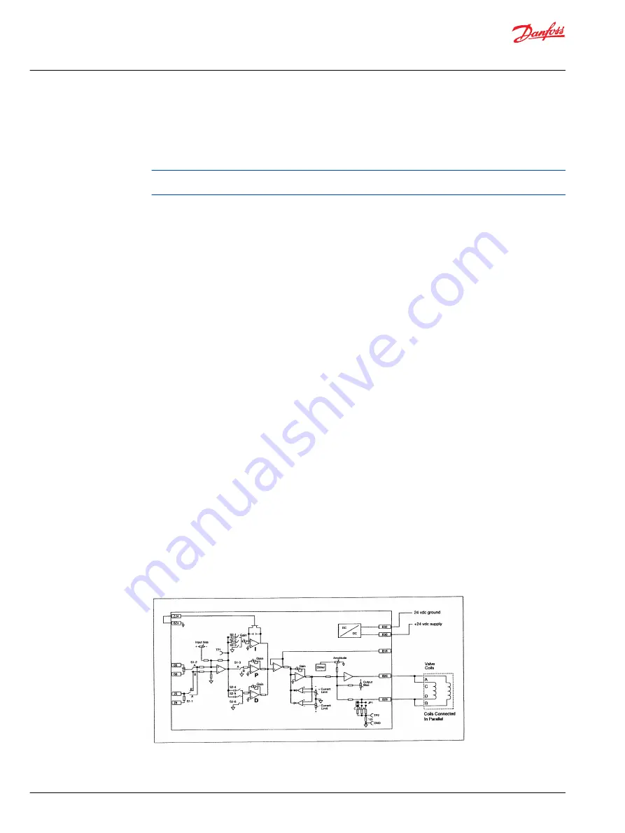
Amplifier Calibration Diagram
Figure 1. Servovalve amplifier set-up connections
Installation Guide
Servo Amplifier
Amplifier Set-up
10 |
©
Danfoss | August 2023
BC459665217198en-000101


