Capacity controller
for digital scroll
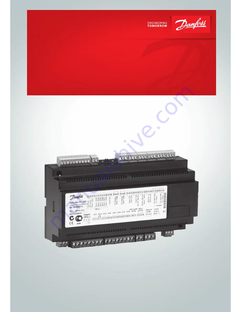
AK-PC 560
User Guide
ADAP-KOOL
®
Refrigeration control systems
Страница 1: ...Capacity controller for digital scroll AK PC 560 User Guide ADAP KOOL Refrigeration control systems ...
Страница 2: ...al indicates that the safety circuit has been activated and the respective circuit stopped Temperature monitoring of the digital scroll compressor Contact inputs for indication of alarms Contact inputs for displacement of references or for indication of alarms Alarm relay External start stop of regulation Possibility of data communication Operation All operation takes place either via data communi...
Страница 3: ...reference Outside the reference a neutral zone is set The digital scroll compressor controls the capacity in the neutral zone in order to maintain the pressure When the digital scroll compressor can no longer maintain the pressure within the neu tral zone the controller will cut out or cut in the next compressor in the row When extra capacity is either cut out or cut in the capacity from the digit...
Страница 4: ...t function connected to the input named ON input The input must be wired r12 Main Switch Condenser regulation reference Condenser control Pc set point Regulation is based on the set value plus an offset if applicable An offset can be cre ated via the r34 function and or from a system units override function r28 PcSet Point C PcSet Point b Offset The set reference may be displaced with a fixed valu...
Страница 5: ...ration Here you set the of number of compressors 1 One compressor 2 two compressors 3 3 4 4 5 5 6 6 7 7 See survey on page 11 c16 Compr mode Selection of coupling mode See also the overview page 11 1 S Sequential First relay 1 cuts in then relay 3 etc Cutout takes place in the oppo site sequence First in last out 2 Cyclic An automatic operating time equalisation is arranged between the remain ing ...
Страница 6: ... value n55 MinSpeed Alarm Alarm settings The controller can give alarm in different situations When there is an alarm the light emitting diodes LED will flash on the display and the alarm relay will cut in In AK PC 560 the alarm relay may be used for a fan if required P0 min Alarm and safety function see also page 20 Here you set when the alarm at too low suction pressure is to enter into effect T...
Страница 7: ...me they must be set in bar P0 Min value o20 P0MinTrsPres P0 Max value o21 P0MaxTrsPres Pc Min value o47 PcMinTrsPres Pc Max value o48 PcMaxTrsPres Use of DI1 input The digital input can be connected to a contact function and the contact can now be used for one of the following functions Setting function 0 DI input not used 1 Fan alarm when contact cuts out Alarm A34 is given 2 Alarm function when ...
Страница 8: ...Set the net frequency o12 50 60 Hz 50 0 60 1 Address If the controller is built into a network with data communication it must have an address and the master gateway of the data communication must then know this address These settings can only be made when a data communication module has been mounted in the controller and the installation of the data communication cable has been completed This ins...
Страница 9: ...ted via data communication In this way the relay output is made available for other applications Boost ready function If two controllers are to capacity regulate the high temperature part and the low temperature part respectively they must be connected in such a way that low temperature regulation cannot be started until the high temperature part is operating The signal can be taken from DO9 of on...
Страница 10: ...anual regulation of outputs 25 S34 Safety cutout Setting A30 is exceeded 34 Alarm messages Alarms Destinations A2 Low P0 A02 Low P0 alarm A11 No refrigerant has been selected cf o30 A11 No RFG Sel A17 High Pc A17 Hi Pc alarm A19 A25 Compr fault Interrupted signal on actual input terminal 29 36 A19 A25 Comp _fault A27 High temperature alarm from sensor Saux The digital scroll is stopped A27 Saux hi...
Страница 11: ...ting c08 will define coupling mode The capacity from the digital scroll compressor The capacity is divided into period times as PWM per 100 capacity is delivered when cooling takes place for the whole period An off time is required by the by pass valve within the period and an on time is also permitted There is no cooling when the valve is on The controller itself calculates the capacity needed an...
Страница 12: ... will become the first fan relay It will be followed by the subsequent relays If more relays are required than the vacant DO relays a relay module can be connected to the analog output The function is as follows 1 2 If there are up to four external fans on an EKC 331 If there are more than four external fans on two EKC 331 units Connection Connection Alternating start up of fans only if c29 is 11 ...
Страница 13: ...e is 2 K or more over the set point EKA 163 If the condensation pressure is to be shown constantly a display without operating keys can be connected EKA 164 To operate the controller and view the evaporation pressure If the lowermost key is pressed the condensation pressure will be shown briefly in the display Like the EKA 165 the LEDs in the display will show where the regulation is located EKA 1...
Страница 14: ...eference displacement r26 99 C 1 0 bar 30 C 40 0 bar 99 9 C 1 0 bar Displacement of P0 ON active r13 r27 OFF ON OFF Pc reference Set regulation set point for Pc r28 25 C 0 0 bar 75 C 110 0 bar 35 C 15 0 bar Shows total Pc reference r29 C bar Limitation Pc reference max value r30 99 9 C 0 0 bar 99 9 C 130 0bar 55 0 C 60 0 bar Limitation Pc reference min value r31 99 9 C 0 0 bar 99 9 C 60 0 bar 99 9...
Страница 15: ...If a higher value is measured then the digital scroll stops A32 1 C 0 OFF 150 C 130 C Delay time for a P0 alarm A44 0 min 1 OFF 480 min 0 min Delay time for a Pc alarm A45 0 min 1 OFF 480 min 0 min Miscellaneous Controllers address o03 1 240 On off switch service pin message o04 Access code o05 1 0 OFF 100 OFF Used sensor type for Saux 1 Internal Copeland NTC A fixed resistor must also be fitted 2...
Страница 16: ...0 3 0 Function for relay output DO10 0 Alarm relay 1 Start stop of condenser fan o76 0 1 0 Definition of alarm message at DI1 signal 0 Not used 1 Fan failure A34 2 DI1 alarm A28 o78 0 2 0 Display connection Off EKA 164 On EKA 165 extended display with light emitting diodes o82 Off On Off Service Temperature at Saux discharge gas temperature u03 Status on DI1 input u10 Status on DI2 input u37 Read ...
Страница 17: ...Terminal 47 interrupted A30 DI 3 alarm Terminal 49 interrupted A31 DI 4 alarm Terminal 50 interrupted A32 DI 5 alarm Terminal 52 interrupted A34 Fan alarm There is no signal on DI1 input A45 Regulation stopped S0 Status message Regulation S2 Wait for c01 S5 Wait for c07 S10 Refrigeration stopped by the internal or external start stop function S25 Manual control of outputs S34 Safety cutout Setting...
Страница 18: ...KA 163 for display of P0 or EKA 165 for operation and display of P0 45 46 DI1 Contact function for alarm signal 45 47 DI2 Contact function for alarm signal 48 49 DI3 Contact function for alarm signal 48 50 DI4 Contact function for displacement of the suction pressure reference or for alarm signal 51 52 DI5 Contact function for displacement of the condenser pressure reference or for alarm signal 51...
Страница 19: ...t is the installer s responsibility to check the installation thoroughly and to fit the necessary safety devices Special reference is made to the necessity of signals to the controller when the compressor is stopped and to the need of liquid receivers before the compressors Your local Danfoss agent will be pleased to assist with further advice etc Dimensions Supply voltage 24 V a c 15 50 60 Hz 5 V...
Страница 20: ...t out 100 capacity Pc Pc max A30 0 capacity 100 capacity Pc signal failure Pc reading 5 No change 100 capacity Sc3 signal failure Variable reference r33 is set to 2 or 4 No change The variable part is omitted Reference r29 Setting r28 Saux Saux Al Lim Compressor cut out No changes Exercising fans On the setting c29 1 8 the last fans will hardly be activated during the winter To ensure that the fan...
Страница 21: ...n Selection of parameter in AK PC 560 084B8013 Sw 1 0x Stop of injection when the compressor is stopped Forced Close Injection ON AKC ON MC Inject ON Night setback Day night control and time schedule r27 NightSetback Suction pressure optimisation P0 optimisation Select controller address The parameters are found automatically and do not become visible The system unit registers the refrigeration po...
Страница 22: ...he temperature approaches this value a cutout of the compressor will be started The different regulation modes are as follows The reference at any time on the basis of which the controller regulates can be seen in r29 A reference r28 is set here which with certainty can cope with all kinds of loads If you need to raise the condensing temperature for say heat recovery an offset value r34 has to be ...
Страница 23: ...reference As 2 but an increasing deviation from the reference must be accepted as the controller uses the difference between the actual condenser temperature and the actual outdoor temperature for indicating the number of fans that has to be cut in The first r56 degrees are left out as there must be a possibility of cooling via the condenser The number of fan steps is divided up based on the Xp va...
Страница 24: ...ility for possible errors in catalogues brochures and other printed material Danfoss reserves the right to alter its products without notice This also applies to products already on order provided that such alternations can be made without subsequential changes being necessary in specifications already agreed All trademarks in this material are property of the respecitve companies Danfoss and Danf...