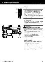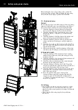
Mixed KSL array configuration
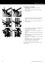
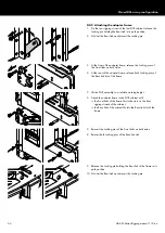
9.2.2 Attaching the adapter frame
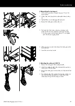
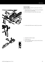
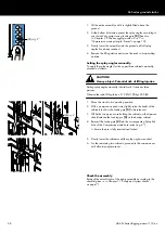
1. On the rear rigging strand of the last SUB cabinet, release the
Locking pin holding the Rear link in its park position.
2. Fold out the Rear link and reinsert the Locking pin.
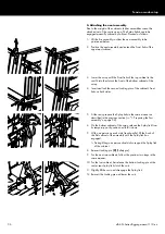
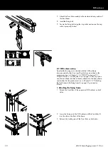
3. At the front of the adapter frame, release the Locking pins of
the Front links on both sides.
4. At the rear of the adapter frame, release both Locking pins of
the Rear link slot of the frame.
5. Lift the SUB assembly to a suitable working height.
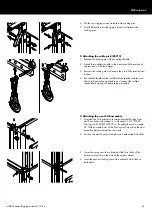
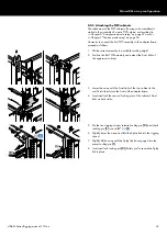
6. Attach the adapter frame to the SUB cabinet until:
▪ the Front links of the frame fit into the slots on the front
rigging strands of the cabinet.
▪ the Rear link of the cabinet fits into the Rear link slot of the
frame.
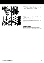
7. Reinsert the Locking pins of the Front links on both sides.
8. Reinsert both Locking pins of the Rear link slot.
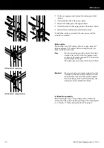
9. Release the Locking pin holding the Rear link of the frame in its
park position.
10. Fold out the Rear link and reinsert the Locking pin.
d&b SL-Series Rigging manual 1.10 en
64
Содержание SL Series
Страница 1: ...SLSL Series Rigging manual 1 10 en ...
Страница 9: ...SL Series rigging modes 2 in 1 Tension mode principle d b SL Series Rigging manual 1 10 en 9 ...
Страница 10: ...SL Series rigging modes 2 in 1 Compression mode principle Preset d b SL Series Rigging manual 1 10 en 10 ...
Страница 79: ...D2734 EN 01 10 2020 d b audiotechnik GmbH Co KG www dbaudio com ...

