SUB columns
8.1 Limitations
NOTICE!
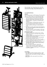
A maximum of:
▪ 14 x SL-SUB
▪ 16 x KSL-SUB
cabinets are allowed to be suspended, including all rigging
components.
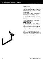
8.2 Rear link of the Flying frames
Rear link position
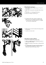
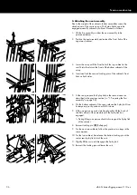
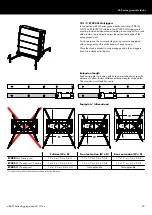
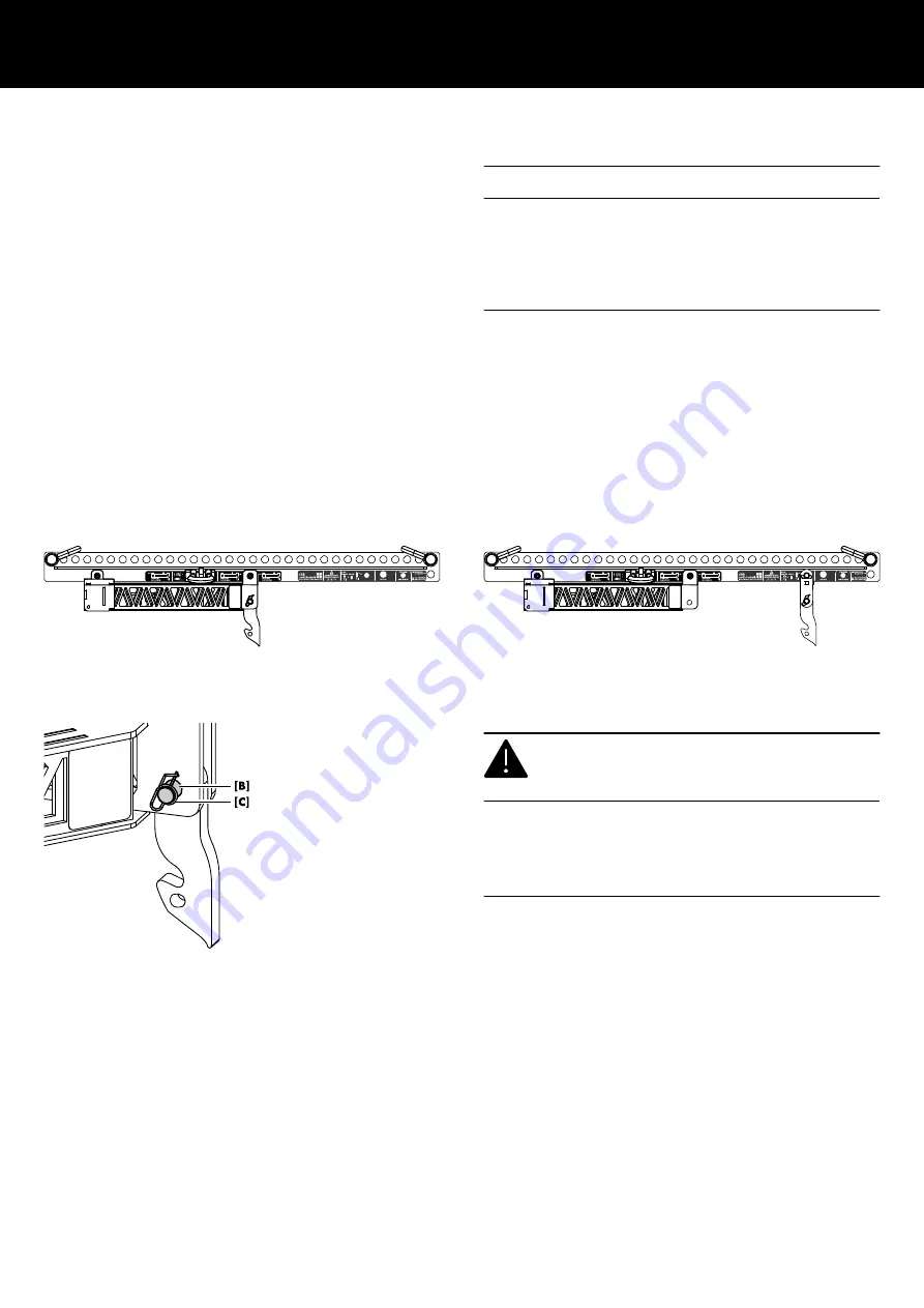
By factory default, the Rear link is attached to the flying frame for
the deployment of applicable TOP cabinets.
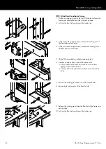
To attach applicable SUB cabinets, the Rear link position has to be
changed and moved to the dedicated hole position on the load
beam. For this purpose, a corresponding adapter (extender) is
provided with the flying frame.
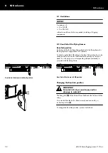
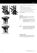
Rear link of the frame in default position
Rear link of the frame in SUB position
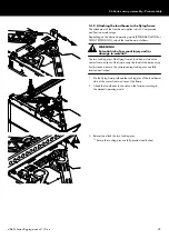
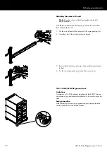
Changing the Rear link position
WARNING!
Potential risk of personal injury and/or
damage to material!
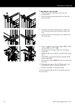
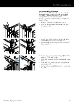
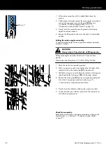
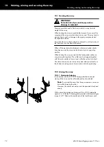
The fixing bolt
[B] of the frame's Rear link bears the full load of the
array.
It is essential that the bolt is fitted correctly and secured by a
locked ring cotter
[C].
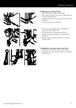
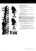
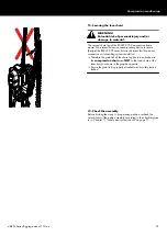
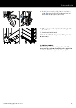
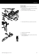
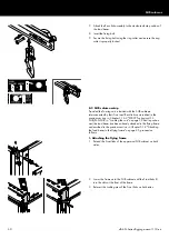
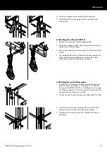
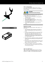
To change the Rear link position, proceed as follows:
8 SUB columns
d&b SL-Series Rigging manual 1.10 en
58
Содержание SL Series
Страница 1: ...SLSL Series Rigging manual 1 10 en ...
Страница 9: ...SL Series rigging modes 2 in 1 Tension mode principle d b SL Series Rigging manual 1 10 en 9 ...
Страница 10: ...SL Series rigging modes 2 in 1 Compression mode principle Preset d b SL Series Rigging manual 1 10 en 10 ...
Страница 79: ...D2734 EN 01 10 2020 d b audiotechnik GmbH Co KG www dbaudio com ...

