Compression mode setup
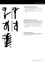
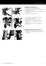
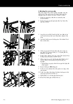
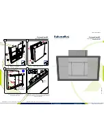
2. Attaching the compression chain
1. Release the Locking pin of the coupling shackle.
2. Attach the coupling shackle to the dedicated hole position at
the rear end of the load beam.
3. Reinsert the Locking pin and ensure the pin is fully inserted and
locked.
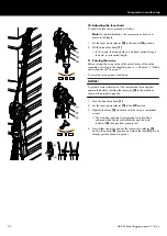
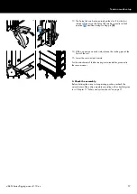
3. Attaching the compression grab link
At a certain point during setup, the compression grab link has to be
attached to the compression chain. Its position depends on the
length and the final curvature of the array and is calculated and
indicated in ArrayCalc («Sources» view
Þ
«Grab link position»).
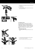
1. Attach the grab link, as shown in the graphic opposite.
2. Ensure the grab link is properly attached and the safety latch
[L] is locked.
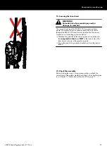
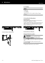
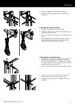
4. Attaching the lever hoist
As opposed to normal operation, the lever hoist is attached upside
down with the hoist's chain hook attached to the grab link, as
shown in the graphic opposite.
d&b SL-Series Rigging manual 1.10 en
48
Содержание SL Series
Страница 1: ...SLSL Series Rigging manual 1 10 en ...
Страница 9: ...SL Series rigging modes 2 in 1 Tension mode principle d b SL Series Rigging manual 1 10 en 9 ...
Страница 10: ...SL Series rigging modes 2 in 1 Compression mode principle Preset d b SL Series Rigging manual 1 10 en 10 ...
Страница 79: ...D2734 EN 01 10 2020 d b audiotechnik GmbH Co KG www dbaudio com ...

