SL-Series rigging components
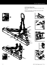
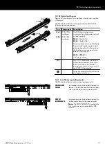
3.3.2 Load beam instruction labels
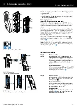
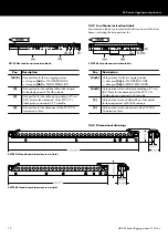
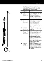
Two instruction labels are located at the bottom strand of the load
beams, indicating the hole positions for:
Z5702 GSL Load beam instruction labels
Z5723 KSL Load beam instruction labels
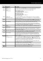
Pos.
Description
[3a/b] Hole positions for the two rigging modes:
▪ Hole pair
[3a] for STANDARD MODE.
▪ Hole pair
[3b] for FRONT EXTENSION.
[4]
Hole position for the additional Rear link adapter
for the deployment of SL-SUB cabinets.
[5]
Hole position for the cable pick providing a 21 mm
(0.8") hole for the attachment of the Z5713 SL
Cable pick or a standard 3.25 t shackle.
[6]
Hole position for the attachment of the Z5709 SL
Compression chain.
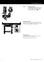
Pos.
Description
[3a/b] Hole positions for the two rigging modes:
▪ Hole pair
[3a] for STANDARD MODE.
▪ Hole pair
[3b] for FRONT EXTENSION.
[4a/b] Hole position for the cable pick providing a 21 mm
(0.8") hole for the attachment of the Z5713 SL
Cable pick or a standard 3.25 t shackle.
[5]
Hole position for the additional Rear link adapter
for the deployment of KSL-SUB cabinets.
[6]
Hole position for the attachment of the Z5709 SL
Compression chain.
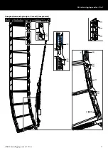
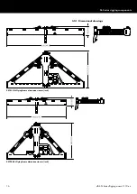
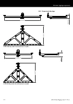
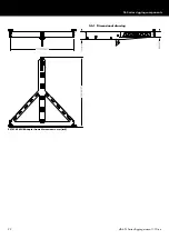
3.3.3 Dimensional drawings
Z5702 GSL Load beam dimensions in mm [inch]
Z5723 KSL Load beam dimensions in mm [inch]
d&b SL-Series Rigging manual 1.10 en
18
Содержание SL Series
Страница 1: ...SLSL Series Rigging manual 1 10 en ...
Страница 9: ...SL Series rigging modes 2 in 1 Tension mode principle d b SL Series Rigging manual 1 10 en 9 ...
Страница 10: ...SL Series rigging modes 2 in 1 Compression mode principle Preset d b SL Series Rigging manual 1 10 en 10 ...
Страница 79: ...D2734 EN 01 10 2020 d b audiotechnik GmbH Co KG www dbaudio com ...

