background image

Hoisting and securing of the array

When all the mechanical adjustments, system checks and safety checks
have been made the array can be hoisted up to its operating position.

When hoisting the array, ensure that the loudspeaker cables do not get
caught anywhere. The cables can be strapped together with the motor
cable to form a loom while the system is hoisted.

The chain hoist motors must raise the system slowly and evenly so that it
does not swing or move from side to side during hoisting.

When the array is in its final operating position the secondary safety
must be applied. A detailed description is given in 3.6 Secondary safety
on page 15.

4.2.2.  Derigging

To lower the array and dismantle it, follow the assembly instructions in
reverse order. The same safety instructions apply.

4.3. 

Variant 3: J-SUB Array

The set up of SUB arrays is carried out in the same manner as
described in section 4.2 Variant 2: J-SUB and J8/J12 Arrays from page
22 (Steps 1 – 21 - Fig. 33a-k.

If desired J-SUB arrays can also be curved. Depending on the chosen
socket for the Locking pins of the J-SUB Front links a splay angle of 0°
(Fig. 36a) or 2° (Fig. 36b) can be applied to the front of the cabinet. The
splay angle of 2° is achieved by the slot in the J-SUB Front links and will
only be effective when the array gets lifted.

4.4. 

Variant 4: J-Series ground stacks

WARNING!

Ground stacked set ups must always be secured against
movement and possible tipping over.

4.4.1.  Limitations for J-Series Ground stacks

The following limitations apply:

A maximum of six J-TOP (J8/J12) cabinets mounted on the J Flying
frame.

A maximum of four J-SUB cabinets and six J-TOP (J8/J12) cabinets
mounted on the J Flying frame on top of the J-SUB cabinets.

4.4.2.  Preparations

For both applications the Splay link of the frame must be fitted in J-SUB
position. Check the position of the Splay link and alter the position if
necessary as described in section 3.4 Splay link position at the Z5300 J
Flying frame on page 12.

J-Series Rigging manual

(1.3 EN)    

Page 26 of 34


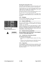
a)

b)

Fig. 36: J-SUB Front Link
Setting of the Locking pins for 0° or 2°

Содержание J Series

Страница 1: ...J Series Rigging manual 1 3 EN...

Страница 2: ...ging manual Version 1 3 EN 05 2012 D2983 EN 01 Copyright 2012 by d b audiotechnik GmbH all rights reserved Keep this manual with the product or in a safe place so that it is available for future refer...

Страница 3: ...J Flying frame 13 3 5 1 J Load adapter 13 3 5 2 Single hoist set up 14 3 5 3 Dual hoist set up 14 3 6 Secondary safety 15 3 6 1 Secondary safety at the Z5300 J Flying frame 15 3 7 Horizontal aiming a...

Страница 4: ...or a total system weight of 665 kg 1466 lb to be flown in any vertical splay angle configuration 1 2 1 ArrayCalc TI 385 For arrays with a total system weight of more than 665 kg 1466 lb the load cond...

Страница 5: ...ngle person lift could cause injury Lifting Hazard Always use assistance when moving or lifting Observe all instructions given on the rigging components Flying frame Load adapter and the loudspeaker c...

Страница 6: ...ing concept 2 1 Z5300 J Flying frame The Z5300 J Flying frame is equipped and supplied with the following rigging components Fig 1 Z5300 J Flying frame top and bottom view J Series Rigging manual 1 3...

Страница 7: ...g a cable pick 1 5 Locking Pins 11 mm Two additional Locking pins 11 mm are supplied with the Flying frame and are located beside the cable pick They are used to connect J Series cabinets on top of th...

Страница 8: ...b Fixing point for the frame s Splay link in J8 J12 position refer to section 3 4 Splay link position at the Z5300 J Flying frame on page 12 The additional hole 2 3b is used to fix the Splay link in i...

Страница 9: ...300 J Flying frame dimensions Fig 4 Z5300 J Flying frame dimensions in mm inch 2 1 4 Dimensions of the Mounting plate 1 3 Fig 5 Mounting plate dimensions in mm inch J Series Rigging manual 1 3 EN Page...

Страница 10: ...of most 2 t motor chain containers and avoids any influence to the vertical balance of the array when suspended from a single pick point Z5305 Specifications Lifting chain 1 leg 10 mm DIN EN 818 Nomi...

Страница 11: ...or faults before use This also includes the loudspeaker and in particular the rigging parts of the cabinets Damaged components must be withdrawn from use immediately Please pay attention to section 6...

Страница 12: ...of the frame to fix the respective component in its park position Connected to the fixing bolt of the respective component with a rue ring cotter and a steel wire Locking pins 10 mm for the two addit...

Страница 13: ...Fig 14 Altering the Splay link position of the frame 3 5 Suspension of the Z5300 J Flying frame 3 5 1 J Load adapter WARNING Before attaching the Load adapter check the 3 25 t shackle is properly fitt...

Страница 14: ...e for the direction of the Load adapter Attaching the Load adapter 1 Choose the appropriate hole position in the J Flying frame center bar according to the ArrayCalc simulation and attach the J Load a...

Страница 15: ...at the cross bar of the frame The latter being the default suspension for the secondary safety are fitted with two 3 25 t shackles We recommend the use of the Z5303 J Safety chain set which is supplie...

Страница 16: ...r forces Refer to section 5 Wind loads on page 30 Fig 24 Safety points of the frame for horizontal aiming and protection against rotation and swing After the array has been lifted to its operating pos...

Страница 17: ...J8 J12 Array Refer to section 4 1 starting from page 18 Variant 2 J SUB and J8 J12 Array Refer to section 4 2 starting from page 22 Alternative variant 3 J SUB Array Refer to section 4 3 starting from...

Страница 18: ...nets before fitting the Flying frame to the top cabinet as described below Fitting the J Flying frame Fig 26 Fig 27a b Fig 28 The J Flying frame can be fitted to the top cabinets Front links using the...

Страница 19: ...o the central rigging strand of the next cabinet Attach the pick point 18 Depending on the type of suspension single or dual hoist set up as described in section 3 5 on page 13 attach the J Load adapt...

Страница 20: ...oard 26 Slightly fold off the board and move it towards the other side to release the fixed pin 27 Take off the wheel board 28 Remove all accessible boards in the same manner 29 Lift the array to get...

Страница 21: ...t to the side handles of the lowest cabinet While lowering the array give direction towards the back of the array to ensure the array will be lowered straight down and safely rolled to the back It is...

Страница 22: ...tion and suspension of the first frame 3 The Splay link of the first frame must be fitted in J SUB position Check the position of the Splay link and alter the position if necessary as described in sec...

Страница 23: ...binet to the respective holes of the Flying frame Fig 33g 16 IMPORTANT Alter the position of the Locking pin at the cabinet as shown in Fig 33h i 17 Fix the Splay link of the frame at the central rigg...

Страница 24: ...ont links 1 7 together with the Locking pins from the park position at the frame 25 Attach the Front links at the top of the front tracks of the frame and fix them with the Locking pins Observe the di...

Страница 25: ...d as follows Preset the desired Splay angle at the respective cabinet 0 6 at the central rigging strand at the rear of the cabinet by inserting the respective Locking pin 7 degrees settings are done w...

Страница 26: ...page 22 Steps 1 21 Fig 33a k If desired J SUB arrays can also be curved Depending on the chosen socket for the Locking pins of the J SUB Front links a splay angle of 0 Fig 36a or 2 Fig 36b can be appl...

Страница 27: ...links of the frame into the rigging tracks at the front of the cabinet and connecting them using the second Locking pins Fig 39a b 6 Remove the wheel board 7 Fold out and insert the Splay link of the...

Страница 28: ...in Raise the back of the cabinet until the Splay link has completely hooked into the Locking pin Insert the second Locking pin to fix the desired splay angle 15 Attach all cabinets in the same manner...

Страница 29: ...nd the Splay link of the frame J SUB position Attaching the J8 J12 cabinets 7 The assembly of the J8 J12 cabinets on top of the J SUB cabinets is carried out in the same manner as described in section...

Страница 30: ...e Large branches in motion whistling heard in telegraph wires umbrellas used with difficulty 7 28 33 50 61 32 38 Near gale Whole trees in motion inconvenience felt when walking against the wind 8 34 4...

Страница 31: ...ng pins with WD 40 or a similar product Front and Splay Rear links Visual inspection regarding deformation and damage e g cracks and corrosion including all drilled holes of the component Z5300 J Flyi...

Страница 32: ...Z5300 J Flying frame including d b J Load adapter d b J Front link Frame d b J Splay link Frame d b J Locking pins d b Z5303 J Safety chain set d b Z5305 J Hoist connector chain d b J Series loudspeak...

Страница 33: ......

Страница 34: ...D2983 EN 01 05 2012 d b audiotechnik GmbH d b audiotechnik GmbH Eugen Adolff Str 134 D 71522 Backnang Germany Phone 49 7191 9669 0 Fax 49 7191 95 00 00_______...

Отзывы: