DANA TM4 SUMO MD MV Скачать руководство пользователя страница 17


Installation Guide 


CONFIDENTIAL 

TG-0057_19 TM4 SUMO HD CO300-A1_A2_A2.5 Installation Guide 

© Dana TM4 inc., 2013-2020 

Page 17 of 42 

2020-11-20 


4.4  Installing the cooling system 

As power is delivered to the wheels, temperatures of the various components within the motor and the 

MCU rise. Therefore, a cooling unit/radiator must be installed in the vehicle and connected to the MCU and 

the motor to dissipate the excess heat.  
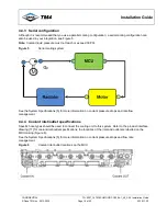
A parallel cooling system is recommended for the TM4 SUMO™ HD system, but information is also given 

on a possible serial cooling configuration, see Section 4.4.3. 

Note

: TM4 does 

not

 supply any cooling equipment or accessories. 

4.4.1  Safety warnings related to handling the cooling agent 

Read all safety warnings associated with handling the cooling agent before working with the cooling 

system. 


WARNINGS


Regardless of the cooling system used, the MCU can be irreparably damaged and may become 

unstable if the coolant liquid pressure reaches or exceeds a pressure of 30 PSI (static pressure 

measured at the entrance of the MCU, upstream of the MCU in the circuit). 

Ensure that the pump is adjusted accordingly.


The cooling agent contains ethylene glycol that is a highly flammable product. Ethylene glycol can 

burn with an invisible flame that can cause serious burns and/or other injuries. 

Always handle the cooling agent carefully wearing appropriate safety clothing and eye-glasses. 

The cooling agent can irritate the skin, the eyes and the mucous membranes. 


Always work in a well-ventilated area when handling the cooling agent; breathing in high 

concentrations of ethylene glycol can cause nausea. 


In case of contact with eyes and skin, rinse with water and consult a doctor. 


In case of ingestion, seek medical help immediately. 

The cooling agent is under pressure when heated; removing the cap when the coolant is hot can 

cause serious burns and/or other injuries. 

Wait until the coolant reaches an ambient temperature before removing the cap. 

All potential dangers of handling cooling agents cannot be listed here. 

Consult manufacturer warnings and recommendations for safe handling of the cooling agent. 

Содержание TM4 SUMO MD MV

Страница 1: ...Installation Guide TG 0057_19 TM4 SUMO HD CO300 A1_A2_A2 5 Installation Guide SUMO HD Product Motor Control Unit MCU Versions CO300 A1 A2 A2 5...

Страница 2: ...TM4 inc 2013 2020 Page 2 of 42 2020 11 20 Product information Product series TM4 SUMO HD Model numbers CO300 A1 CO300 A2 CO300 A2 5 Document information Reference TG 0057 TM4 CO300 A1_A2_A2 5 Installa...

Страница 3: ...sing separate brackets to support MCU and motor 13 4 2 2 Respecting the physical integrity of the MCU 13 4 2 3 Protecting the casing from external loads 13 4 2 4 Correctly positioning the MCU 13 4 3 S...

Страница 4: ...nstallation Guide Dana TM4 inc 2013 2020 Page 4 of 42 2020 11 20 4 6 Software installation 40 4 6 1 Selecting communication protocol type 40 4 6 2 CAN protocol and TM4 ODIN 40 4 6 3 Embedded software...

Страница 5: ...ecifications 30 Table 8 HVIL and EmergencyStop Absolute maximum rating 31 Table 9 High voltage battery Recommended fuse sizing 35 Table 10 CO300 model number vs internal common mode capacitor type 35...

Страница 6: ...19 Figure 7 Grounding point 24 Figure 8 Phase cable gland locations 25 Figure 9 Motor sensor interface location Base of the MCU 27 Figure 10 Front of connector 28 Figure 11 VMU ECU interface location...

Страница 7: ...e TM4 SUMO HD CO300 MCU 1 2 Scope This technical guide is divided as follows Introduction general information about the product definitions and document reference information Transport and storage con...

Страница 8: ...one safety warning applies to the same procedure they are grouped together in one box and identified with the appropriate safety symbol General Irritant Operational This warning symbol indicates that...

Страница 9: ...ations and Maintenance Guide 1 5 TG xxxx TM4 SUMO HD System Specifications 1 2 6 Application Note TM4 SUMO Fuse and DC Cable Selection 1 7 SC 6000E 036 Kit 0076 VMU interface connector assembly instru...

Страница 10: ...cts must be transported and stored in well ventilated facilities with adequate protections against dust and excessive humidity See Table 2 details of recommended conditions While the products are in t...

Страница 11: ...2 Inspecting and moving the MCU 1 On receiving the MCU immediately verify that the crate is undamaged if you see signs of damage before signing for the package Inform the person delivering the packag...

Страница 12: ...guide on how to install the MCU Call TM4 Customer Service if in doubt see Section 5 for contact details 4 1 1 Respecting CSC and MKC markings on interface drawings Before installing the product refer...

Страница 13: ...tomization before or after installation You must not under any circumstances attempt to modify any part of the MCU as this could cause permanent damage to the MCU and injury to the user This includes...

Страница 14: ...Page 14 of 42 2020 11 20 Figure 1 Position of vent on base of MCU casing Figure 2 Position of IGBT coolant overflow holes on base of MCU casing Note In case of any sign of coolant leakage from these p...

Страница 15: ...M4 regarding the product must be respected Do not attempt to open or repair this product In case of damaged casing or suspected product malfunction contact TM4 Use only indicated points to secure the...

Страница 16: ...0 A1_A2_A2 5 Installation Guide Dana TM4 inc 2013 2020 Page 16 of 42 2020 11 20 Figure 3 Mounting points External view of top and base of the MCU Note Mounting points can also be used as lifting point...

Страница 17: ...or exceeds a pressure of 30 PSI static pressure measured at the entrance of the MCU upstream of the MCU in the circuit Ensure that the pump is adjusted accordingly The cooling agent contains ethylene...

Страница 18: ...are supplied by the vehicle integrator and the cooling system setup involves fine tuning and testing at the customer site TM4 has no specific recommendations on how to achieve optimum configuration b...

Страница 19: ...0 PSI Figure 5 Serial cooling system See the System Specifications 5 for more information on coolant pressure drops and rate flow management 4 4 4 Coolant inlet outlet specifications Specific hose typ...

Страница 20: ...ion ASTM D3306 Type III or ASTM D6210 Type III The ethylene glycol must contain some type of active corrosion inhibitors The ethylene glycol must be diluted with de ionized water not distilled water T...

Страница 21: ...ance with applicable vehicle standards and industry practices Always use appropriate insulation and protection before manipulating the product even when the product is disconnected from a high voltage...

Страница 22: ...sure that cables do not touch or cross over each other Never place cables near sharp edges or on abrasive surfaces Protect cables from damage due to gravel or other environmental factors Allow for eno...

Страница 23: ...r source is enabled Note Reverse sequencing is performed when removing the system from the vehicle remove the grounding strap last 4 5 4 Grounding the system The system must be securely grounded to en...

Страница 24: ...3 before insertion One screw is provided for grounding purposes Table 4 Grounding strap installation First end Second end Refer to Figure 7 Vehicle chassis frame or earth ground test bench Note The lo...

Страница 25: ...reparation before installation For detailed cable end preparation information see the cable end specification document for your installation 7 Note Phase cables can be up to a length of 5 m 4 5 5 2 In...

Страница 26: ...Motor MCU Motor MCU A1 1 A1 9 B1 2 B1 8 C1 3 C1 7 A2 4 A2 6 B2 5 B2 5 C2 6 C2 4 A3 7 A3 3 B3 8 B3 2 C3 9 C3 1 Notes 1 If the reversed connection scenario is chosen the PhaseCableReversed parameter mus...

Страница 27: ...obtain specially designed adaptors from TM4 that allow you to combine a prototype motor with an Alpha version MCU or a prototype MCU with an Alpha version motor Contact TM4 Customer Service for more...

Страница 28: ...or interface pinout information The following information may be required for troubleshooting purposes Table 6 gives the mapping between the pins on the TM4 motor and the TM4 MCU Figure 10 shows the p...

Страница 29: ...N ports The VMU interface is located on the left side of the MCU next to the motor sensor interface Figure 11 and has 14 pins Figure 11 VMU ECU interface location Underside of the MCU As vehicle integ...

Страница 30: ...CAN1H Communication 20 22 High level of differential signal CAN1 C CAN2L Communication 20 22 Low level of differential signal CAN2 D CAN2H Communication 20 22 High level of differential signal CAN2 J...

Страница 31: ...PORTANT NOTE Depending on the product model number of the TM4 inverter you are using there are two possible default factory settings either Vaux or Vaux and therefore two possible EmergencyStop scenar...

Страница 32: ...is maintained at Vaux Chassis level for a minimum of 10 seconds After this period of time and as long as the MCU is kept enabled IGNITION input at Vaux level this signal will only go at high impedanc...

Страница 33: ...gnal is maintained at Vaux level for a minimum of 10 seconds After this period of time and as long as the MCU is kept enabled IGNITION input at Vaux level this signal will only go at high impedance if...

Страница 34: ...with your integration 4 5 8 1 Safety instructions related to connecting the high voltage battery Carefully read all safety instructions before connecting the high voltage battery WARNINGS This produc...

Страница 35: ...ment varies depending on the model of CO300 you are using Table 10 CO300 model number vs internal common mode capacitor type Model number Capacitor INV HP2HV_0309 xx A1 INV HP2HV_0309 03 A2 2 1 F 20 I...

Страница 36: ...INV HP2HV_0309 05 A2 5 645 5 INV HP2HV_0309 06 A1 645 5 INV HP2HV_0309 07 A1 945 5 INV HP2HV_0309 13 A1 645 5 INV HP2HV_0309 14 A1 945 5 INV HP2HV_0309 15 A1 945 5 INV HP2HV_0309 16 A2 5 945 5 The ve...

Страница 37: ...integrator before installing them in the MCU Refer to the cable end specifications 12 for preparation instructions for both the negative and positive cable ends 4 5 8 7 Installing the high voltage ba...

Страница 38: ...power the MCU The negative terminal of the battery must be connected to the frame of the vehicle chassis To protect the system against short circuit add a fuse in series with the positive terminal of...

Страница 39: ...Guide Dana TM4 inc 2013 2020 Page 39 of 42 2020 11 20 4 5 10 CAN interface The integrator must select impedance according to the desired CAN bus terminations CAN1 is terminated see Figure 18 CAN2 is n...

Страница 40: ...ormation 4 6 2 CAN protocol and TM4 ODIN The TM4 CO300HV A MCU uses the CAN protocol to send and receive messages data Although certain aspects of the protocol have default settings at the time of del...

Страница 41: ...EED_OPTION in Parameters Drive CanBaudRate in TM4 ODIN 2 Save the new value with the Parameters Command DrvParameters Save command Note The system must be shut down and then restarted for the changes...

Страница 42: ...e TM4 CO300HV MCU from the list 6 Click on the Apply button 7 From the TM4 ODIN menu select Tools Flash program manager Note A message is displayed asking if you want to save the current workspace bef...

Отзывы: