background image


52  


Camera Performance and Features  

Built-In Self-Test Codes (BIST) 

In the Camera Information screen shot example above, the Power-On Status is showing the 23 

status flags where ‘1’ is signaling an issue. When there are no issues, the Power-On status will 

indicated “Good”. 


Details of the BIST codes can be found in the Trouble Shooting Guide in Appendix B. 

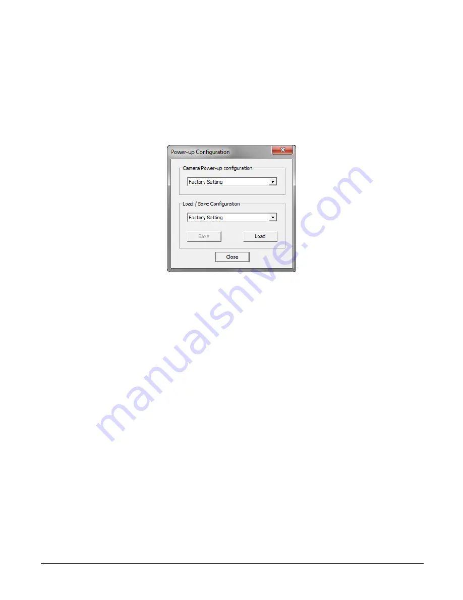
Camera Power-Up Configuration Selection Dialog 


CamExpert provides a dialog box which combines the menu option used to select the camera’s 

power-up state and the options for the user to save or load a camera state as a specific user set 

that is retained in the camera’s non-volatile memory.   

Camera Power-up Configuration 

The first drop list selects the camera configuration state to load on power-up (see feature 

UserSetDefaultSelector

). The user chooses from the factory data set or from one of 16 available 

user-saved states.  

User Set Configuration Management 

The second drop list allows the user to change the camera configuration any time after a power-up 

(see feature 

UserSetSelector

). To reset the camera to the factory configuration, select 

Factory Set


and click Load. To save a current camera configuration, select User Set 1 to 16 and click Save. 
Select a saved user set and click Load to restore a saved configuration.   

Camera Control Category 

The camera control category, as shown by CamExpert, groups control parameters such as line rate, 
exposure time, scan direction, and gain.  

Содержание Linea ML ML-FM-08K30H-00-R

Страница 1: ...Linea ML Multiline Cameras Monochrome HDR CMOS ML FM 08K30H and ML HM 16K30H sensors cameras frame grabbers processors software vision solutions 03 032 20263 00 w ww teledynedalsa com ...

Страница 2: ...rkets digital imaging products and solutions in addition to providing wafer foundry services Teledyne DALSA Digital Imaging offers the widest range of machine vision components in the world From industry leading image sensors through powerful and sophisticated cameras frame grabbers vision processors and software to easy to use vision appliances and customvision modules Contact Teledyne DALSA Tele...

Страница 3: ...FIGURE FRAME GRABBER SOFTWARE 16 Using Sapera CamExpert 16 CamExpert Panes 17 SETTING UP FOR IMAGING 20 Powering the Camera 20 Power and GPIO Connections 21 Establishing Camera Communications 23 Selecting the Data Format 23 Establishing Data Integrity 23 CAMERA PERFORMANCE AND FEATURES 25 SYNCHRONIZING TO OBJECT MOTION 25 Acquiring Images Triggering the Camera 25 Measuring Line Rate Trigger 25 Max...

Страница 4: ... 45 USING TWO CLHS CABLES 46 SAVING RESTORING CAMERA SETUP CONFIGURATIONS 46 Active Settings for Current Operation 47 User Setting 47 Factory Settings 47 Default Setting 48 APPENDIX A GENICAM COMMANDS 49 Camera Information Category 49 Camera Information Feature Descriptions 50 Built In Self Test Codes BIST 52 Camera Power Up Configuration Selection Dialog 52 Camera Power up Configuration 52 User S...

Страница 5: ...Linea ML Multiline Monochrome HDR CMOS Cameras 5 Causes for Overheating Power Shut Down 76 DECLARATION OF CONFORMITY 78 DOCUMENT REVISION HISTORY 79 ...

Страница 6: ...and cable flexing requirements LC or CX4 resolution dependent Teledyne DALSA s Linea ML cameras and compatible frame grabbers combine to offer a complete solution for the next generation of automatic optical inspection AOI systems This camera is recommended for detecting small defects at high speeds and over a large field of view in LCD and OLED flat panel displays printed circuit boards film prin...

Страница 7: ...CX4 16K Camera Link HS control data connector Smart lens shading correction High dynamic LUT mode Programmability Spatial correction including sub pixel adjustment Parallax correction Multiple areas of interest for data reduction Region of interest for easy calibration of lens and shading correction Test patterns diagnostics Applications Flat panel LCD and OLED display inspection Web inspection Pr...

Страница 8: ...a GenICam support XML camera description file Embedded w ithin camera Sapera LT including CamExpert GUI application and GenICam for Camera Link imaging driver Latest version on the TeledyneDALSA Web site Performance Specifications Table 4 Camera Performance Specifications Specifications ML FM 08K30H ML HM 16K30H Imager Format High speed CMOS multiline sensor Resolution 8 192 x 4 pixels mono 16 384...

Страница 9: ...s required Full Well Low Responsivity Line High Responsivity Lines 44 000 e typical single row 7 200 e typical single row PRNU 2 50 of calibration target FPN 2 DN SEE Low Responsivity Line High Responsivity Lines 90 nJ cm 2 14 nJ cm 2 NEE Low Responsivity Line High Responsivity Lines 100 pJ cm 2 17 pJ cm 2 Anti blooming 100x Saturation Integral non linearity 2 DN digital number Test Conditions unl...

Страница 10: ...ructure Forward and reverse imaging does not cause the optical center to change Exposure control allows inspectionspeed to change without changing responsivity Camera Processing Chain The diagram below details the sequence of arithmetic operations performed on the cameras sensor data which the user can adjust to obtain an optimum image for their application These adjustments are performed using ca...

Страница 11: ...ial digital camera interfaces with a single or multiple frame grabbers and with data rates exceeding those supported by the standard Camera Link The cameras come with two different output mediums The 8K camera uses two LC connectors for data output These two LC connectors are part of the SFP standard but in the case of Linea ML 8K camera the SFP modules are built into the camera Either one or both...

Страница 12: ...ormation Category Fiber Diameter Mode Max Distance OM1 62 5µm Multimode 33m OM2 50 µm Multimode 85m OM3 50 µm Multimode 280m CX4 AOC 16K Cameras For the 16K camera the Camera Link HS CX4 AOC Active Optical Cable cables are made to handle very high data rates These cables accept the same electrical inputs as traditional copper cables but also use optical fibers AOC uses electrical to optical conver...

Страница 13: ...Linea ML Multiline Monochrome HDR CMOS Cameras 13 Responsivity QE Plots Figure 3 Camera Spectral Responsivity Figure 4 Camera Quantum Efficiency Note values measured using 8 bit 1x gain single row ...

Страница 14: ...14 Linea ML Multiline Monochrome HDR CMOS Cameras Mechanical Drawings Figure 5 Linea ML FM 8K Camera Mechanical ...

Страница 15: ...Linea ML Multiline Monochrome HDR CMOS Cameras 15 Figure 6 Linea ML HM 16K Camera Mechanical ...

Страница 16: ...the surface finish Though this camera supports hot plugging it is recommended that you power down and disconnect power to the camera before you add or replace systemcomponents Electrostatic DischargeandtheCMOS Sensor Image sensors and the camera s housing can be susceptible to damage from severe electrostatic discharge ESD Electrostatic charge introduced to the sensor window surface can induce cha...

Страница 17: ... run a separate acquisition program For context sensitive help click on the button and then click on a camera configuration parameter A short description of the configuration parameter will be shown in a popup Click on the button to open the help file for more descriptive information on CamExpert Note The availability of features depends on the CamExpert user setting Not all features are available...

Страница 18: ... included with the Sapera installation or saved by the user Parameters pane Allows the viewing or changing of all acquisition parameters supportedby the acquisition device CamExpert displays parameters only if those parameters are supported by the installed device This avoids confusion by eliminating parameter choices whenthey do not apply to the hardware in use Display pane Provides a live or sin...

Страница 19: ...uffer data Stretch image to fit set image display to original size or zoom the image to virtually any size and ratio Histogram Profile tool Select to view a histogram or line column profile during live acquisition or in a still image Output Message Pane Displays messages fromCamExpert or the device driver At this point you are ready to start operating the camera acquire images set camera functions...

Страница 20: ...ngtheCamera WARNING When setting up the camera s power supply follow these guidelines Apply the appropriate voltages of between 12 V to 24 V with a 5 tolerance Incorrect voltages may damage the camera Before connecting power to the camera test all power supplies Protect the camera with a 3 amp slow blow fuse between the power supply and the camera Do not use the shield on a multi conductor cable f...

Страница 21: ...when looking at the camera s 12 pin male Hirose connector The table below lists the I O signal connections 1 4 6 7 12 11 3 2 10 8 9 5 Pin Number Input Output Signal Details Notes 1 Pow er Ground 2 12 V to 24 V pow er 3 Output Line 3 Out 0 to 3 3V TTL 4 Output Line 4 Out 0 to 3 3V TTL 5 Input Line 1 Trigger Phase A 0 to 3 3V TTL 6 Input Line 2 Scan Direction Phase B 0 to 3 3V TTL 7 Output Line 5 Ou...

Страница 22: ... Cable Assembly Teledyne DALSA makes available for purchase an optional GPIO breakout cable 12 pin Female Hirose to 13 Pos Euro Block as shown in the following drawing Use accessory number CR GENC IOP00 to order External Input Electrical Characteristics Switching Voltage Input Level Standard Low to high High to low Input Impedance 3 3V TTL 2 1V 1V 10K Ω External Input Timing Reference Input Level ...

Страница 23: ... Red The camera has stopped output and has shut dow n some components due to an over temperature condition Blinking Orange Pow ering Up The microprocessor is loading code Blinking Green Hardw are is good but the CLHS connection has not been established or has been broken Constant Green The CLHS Link has been established and data transfer may begin When the camera s LED state is steady green open C...

Страница 24: ... a frame grabber CamExpert instance to capture display and analyze the test pattern image to verify the integrity of the connection If the test pattern is not correct check the cable connections and the frame grabber setup 4 Disable the test pattern output ...

Страница 25: ... Link HS frame grabber or from the rotary encoder feature using pin 5 and pin 6 of the GPIO connector Use the Trigger Activation feature to select the edge or level that triggers the camera The options are Rising Edge Falling Edge or Any Edge CamExpert can be used to configure the frame grabber for routing the encoder signal from the frame grabber input to the trigger input of the camera via the C...

Страница 26: ...Rate The minimum line rate for all camera models is 0 kHz Cameras go to full stop without image anomaly Scan Direction See the section Camera Control Category in Appendix A for GenICam features associated with this section and how to use them Related Feature sensorScanDirectionSource sensorScanDirection A multiline camera requires the user to tell the camera the direction of travel of the object b...

Страница 27: ...Camera Performance and Features 27 Figure 9 Image with incorrect scan direction ...

Страница 28: ... of the lens the direction of the objects motion is opposite to the image motion direction Some AOI systems require that the scan direction change at regular intervals For example scanning a panel forwards coming to a stop and then scanning backward as the camera s field of view is progressively indexed over the entire panel It is necessary for the systemto over scanthe area being imaged including...

Страница 29: ... equal to the object pixel Line Spatial Correction will be 1 However guaranteeing the encoder pulse accuracy may not always be possible In addition lens magnification may not be exact which will introduce a similar error The camera has a Line Spatial Correction feature that can correct for these small encoder or magnification errors on a sub pixel level The sub pixel spatial correction resolution ...

Страница 30: ...encoder pulse will not provide the correct timing for all the cameras For example as the camera angle moves away fromperpendicular the image row spacing increases If the encoder resolution remains at that for perpendicular operation many encoder pulses will be too closely spaced apparent row spacing will increase and the line spatial correction will need to change The Line Spatial correction featu...

Страница 31: ...ax If the camera angle and the lens angular field of view are sufficiently large it may cause blurring at the extremities of the image in TDI mode The camera includes a Parallax feature that cancorrect these artifacts Figure 12 Camera Angle Creates Parallax Notes The selection of the line to adjust is dependent on positive or negative angle It is not sensitive to scan direction Projected Line Obje...

Страница 32: ...Pixel Spatial Correction 9 2 No Parallax Correction Establishing the Desired Response One of the important performance characteristics of the camera that will determine its suitability for an application is its responsivity and the associatednoise level at the system s maximum line rate and under the desired illumination conditions and lens configuration ...

Страница 33: ...l Timed is the standard exposure operation as found in Teledyne DALSA line scan cameras For operation of sequential mode please see the section titled Exposure Mode Sequential See the Exposure Control Section Line RateJitter If the exposure time is close to the line period there could be jitter in the line rate when it is synchronizedto the sensor clock if ExposureMode Timed With Exposure mode off...

Страница 34: ... IO Control category Set the row with the LineSelector feature Set the outputLineSource to On And then set the outputLinePulseDelay outputLinePulseDuration and LineInverter ExposureTimeSelector See the section Camera Control Category in Appendix A for GenICam features associated with this section and how to use them Relevant Feature ExposureTimeSelector The Exposure Time Selector allows the user t...

Страница 35: ...Camera Performance and Features 35 Linea ML Object to Image Bright Field Illumination Dark Field Illumination Back Field Illumination Figure 13 Typical Lighting Configuration ...

Страница 36: ...atures The TriggerDelay feature delays the trigger going to the sensor This delay allows the user to turn on the LED before exposing the sensor Each line can be delayed relative to the previous line using the ExposureDelay feature Note The ExposureDelay feature can only be applied to the second third or fourth lines being exposed The exposures for each line cannot overlap Camera TriggerIn Sensor T...

Страница 37: ...obe source in order to coordinate with the sensor exposure AdjustingResponsivity See the section Camera Control Category in Appendix A for GenICam features associated with this section and how to use them Relevant Features Gain Selector Gain It is desirable for camera performance to always use the maximum exposure time possible based on the maximum line rate of the inspection systemand any margin ...

Страница 38: ...libration is set to a target level that is lower than the peak value and the systemgain is set to a low value then it is possible that the sensor will maximize its output before the camera s output reaches 255 DN This can be seen when a portion of the output stops increasing before reaching 255 DN with increasing illumination and the PRNU deteriorates This effect can be resolved by decreasing the ...

Страница 39: ... used by the camera as soon as they are uploaded To avoid loss at power up or while changing row settings the uploaded coefficients should be saved to one of the available user sets Flat Field Calibration Filter See the section Flat Field Category in Appendix A for GenICam features associated with this section and how to use them Related Feature Calibration Algorithm If a sheet of material is bein...

Страница 40: ...ed TDI Stage Selections and Full Well See the section Camera Control Category in Appendix A for GenICam features associated with this section and how to use them Relevant Features sensorTDIMode sensorTDIStagesSelection sensorFullWellMode The camera s sensor has 3 high responsivity lines These line scan be summed to further increase the responsivity The TDI Stage Selection feature with values of 1 ...

Страница 41: ...actor Suggestion for ScaleFactor is 250 expected peak value of row0 range 1 4 Image Filters Related Features imageFilterMode imageFilterType imageFilterKernalSize imageFilterContrastRatio The camera has a selection of image filters that can be used to reduce image noise Use the feature imageFilterMode to turn the filtering on or off Use the feature imageFilterType to read the user information of t...

Страница 42: ...in applications lower image resolution may be acceptable if the desired defect detection can still be achieved Binning is a process whereby adjacent pixels are summed The camera supports 1x 2x and 4x binning in both horizontal and vertical directions Vertical Binning is achieved by the camera summing consecutive lines Horizontal binning is achievedby averaging adjacent pixels in the same line 2x b...

Страница 43: ... to the sum of the individual AOIs The frame grabber will need to be adjusted to accommodate the smaller overall image width As the host computer defined the size of each individual AOI s it will be able to extract and process each individual AOI from the single larger image Steps to Setup Area of Interest 1 Plan your AOIs 2 Stop acquisition 3 Set the number of AOIs 4 Select the first AOI and set ...

Страница 44: ... mode of the camera Further when the LUT is enabled it is recommended that the fixed Offset available in the Camera Control category be set to zero To upload a LUT use File Access Control Category Upload Download File Settings and select Look Up Table to upload a file The file format is described in 03 084 20133 Linea ML Binary File Format which can be obtained from Teledyne DALSA Technical Suppor...

Страница 45: ...onsivity to achieve the desired output fromthe camera The camera has a gain feature that can be used to adjust the camera s responsivity Gain adjustment is available to independently adjust each line or all of them together SystemGain can be adjusted from1 to 10x Individual line gains can be adjusted from 1 to 4x When an image contains no useful dark image data below a specific threshold then it m...

Страница 46: ...power cycling the camera or reconnecting the cables Saving Restoring Camera Setup Configurations See the section Camera Information Category in Appendix A for GenICam features associatedwith this sectionand how to use them Related Features Power upConfiguration Selector UserSet1 thru UserSet16 User Set Selector Power on User Set Current User Set An inspection systemmay use multiple illumination re...

Страница 47: ...e command user set save saves the current settings to non volatile memory as a user set The camera automatically restores the user set configured as the default set when it powers up To restore a saved user set set the user set selector to the set you want to restore and then select the user set load parameter Factory Settings The factory setting is the camera settings that were shipped with the c...

Страница 48: ...when the camera is powered up Either the factory or one of the user settings can be used as the default setting by selecting the set to use in the user set default selector The chosen set automatically becomes the default setting and is the set loaded when the camera is reset or powered up ...

Страница 49: ... device the feature was introduced Additionally the Device Version column will indicate which parameter is a member of the DALSA Features Naming Convention using the tag DFNC versus the GenICam Standard Features Naming Convention SFNC tag not shown In the CamExpert Panes parameters in gray are read only either always or due to another parameter being disabled Parameters in black are user set in Ca...

Страница 50: ... Information Panel Camera Information FeatureDescriptions Display Name Feature Description Device Version View Model Name DeviceModelName Displays the device model name RO 1 00 Beginner Vendor Name DeviceVendorName Displays the device vendor name RO 1 00 Beginner Part Number deviceManufacturesPartNumber Displays the device vendor part number RO 1 00 Beginner Device Version DeviceVersion Displays t...

Страница 51: ...6 or factory set that is loaded or saved w hen the UserSetLoad or UserSetSave command is used 1 00 Beginner Load Configuration UserSetLoad Loads the camera configuration set specified by the User Set Selector feature to the camera and makes it active W 1 00 Beginner Save Configuration UserSetSave Saves the current camera configuration to the user set specified by the User Set Selector feature The ...

Страница 52: ...camera s non volatile memory Camera Power upConfiguration The first drop list selects the camera configuration state to load on power up see feature UserSetDefaultSelector The user chooses fromthe factory data set or from one of 16 available user saved states User Set ConfigurationManagement The second drop list allows the user to change the camera configuration any time after a power up see featu...

Страница 53: ...ptions Display Name Feature Description Device Version View Device Scan Type Linescan DeviceScanType Used to set the camera scanning mode Only standard line scan mode is available RO 1 00 Beginner SNFC Sensor Color Type sensorColorType Identifies the sensor color type Monochrome RO 1 00 Beginner ...

Страница 54: ... 00 Beginner Full Well Mode sensorFullWellMode Selects betw een low and high full w ell sensor row w hen TDI Stages is one Low full w ell is four times more responsive 1 00 Beginner HDR Scale Factor hdrScaleFactor Multiply HDR image by this factor 1 00 Beginner Exposure Mode ExposureMode Sets the operation mode for the camera s exposure or shutter RO 1 00 Beginner Timed Sequential Timed Sequential...

Страница 55: ... is applied to Overall camera gain applied to every sensor line equally Gain applied to all sensor lines Gain applied to all sensor row 0 only Gain applied to all sensor row 1 only Gain applied to all sensor row 2 only Gain applied to all sensor row 3 only 1 00 Beginner Gain Gain Sets the gain as per the gain selector setting 1 00 Beginner Black Level BlackLevel Controls the black level as an abso...

Страница 56: ...on PixelStretch The stretch value in pixels at the ends of line one or three Note the stretch value for line tw o is alw ays half that of the stretch value regardless of w hich line is selected 1 00 Expert Save Image To Flash saveLastImageToFlash Captures the current line and saves it to the cameras Flash memory as a TIFF file that can be retrieved using the File Access Control Features 1 00 Guru ...

Страница 57: ...ling edge of the line source signal The trigger is considered valid on any edge 1 00 DFNC Beginner Rotary Encoder Direction Counter Clockw ise Clockw ise rotaryEncoderDirection CounterClockw ise Clockw ise Specifies the phase w hich defines the encoder forw ard direction Inspection goes forw ard w hen the rotary encoder direction is counter clockw ise phase A is ahead of phase B Inspection goes fo...

Страница 58: ...he physical line or pin of the external device connector to configure External trigger or rotary encoder A External direction or rotary encoder B Output 1 Output 2 Output 3 Output 4 1 00 DFNC Beginner Output Line Source Off On outputLineSource Off On Selects w hich internal signal to output on the selected line Current output line is set w ith outputLineSoftw areCmd Current output line is configur...

Страница 59: ...ers used to control the FPN and PRNU calibration process Figure 23 Flat Field Panel Flat Field Control Feature Description Display Name Feature Description Device Version View Flat Field Correction Mode flatfieldCorrectionMode 1 00 Off FPN and PRNU correction disabled Beginner On FPN and PRNU correction enabled DFNC Clear Coefficents flatfieldCalibrationClearCoefficient Reset all FPN to 0 and all ...

Страница 60: ... filter this algorithm is not able to correct pixel to pixel variations and so it is preferable to use the Target algorithm Flat Field Calibration Target flatfieldCalibrationTarget Sets the target value for the Calibrate PRNU feature Flat Field ROI Offset X flatfieldCalibrationROIOffsetX Set the starting point of a region of interest w here a flat field calibration w ill be performed 1 00 Beginner...

Страница 61: ...a Correction Gamma Correction The output LUT is populated using the gamma correction equation User Defined User Defined LUT uploaded by the user is used Gamma Correction gammaCorrection The output LUT is populated using the follow ing gamma correction equation 𝐷𝑁𝑜𝑢𝑡 255 𝐷𝑁𝑖𝑛 255 1 𝛾 1 00 Beginner DFNC Image Filter Mode imageFilterMode Enable image filter Image Filter Type imageFilterType Read only...

Страница 62: ...O 1 00 Beginner DFNC Line Select ComponentSelect Select line 0 3 to enable w hen in planar mode Line Enable False True ComponentEnable False True Enable disables the selected line Available only in planar mode 1 00 Beginner DFNC Sensor Width WidthMax Indicates the maximum number of pixels available in the long line axis the sensor Read only 1 00 Beginner DFNC Horizontal Offset OffsetX Output image...

Страница 63: ...orizontal and vertical raps to form a diagonal grey scale User Pattern User Pattern User can define a test pattern by uploading to the camera a PRNU file using the FileAccess Miscellaneous User PRNU feature The PRNU coefficient w ill be applied to a midscale 128DN test image AOI Count multipleROICount Specified the number of AOI s in an acquired image 1 to 4 1 00 Beginner SFNC AOI Selector multipl...

Страница 64: ...orVersion Together w ith DeviceManifestXMLMinorVersion specifies the GenICam feature description XML file version RO 1 00 Beginner DFNC XML Minor Version DeviceManifestXMLMinorVersion Together w ith DeviceManifestXMLMajorVersion specifies the GenICam feature description XML file version RO 1 00 Beginner DFNC Refresh GenCP Status refreshGenCPStatus Press to update the GenCP Status 1 00 Beginner ...

Страница 65: ...fter pow er up POGO Pow er On GO mode as soon as the camera detects a cable it enables its transmitters and starts sending image data Camera w aits for LL_Device_ID to be set before enabling its transmitters User must then read XML and all features and then send an Acquisition Start before the camera w ill send image data 1 00 Guru DFNC Next CLHS Device Configuration One cable five lanes One cable...

Страница 66: ...to capture during an acquisition and the w ay it stops Only continuous mode is currently available 1 00 Beginner DFNC Acquisition Start AcquisitionStart Commands the camera to start sending image data WO 1 00 Beginner DFNC Acquisition Stop AcquisitionStop Commands the camera to stop sending image data at the end of the current line WO 1 00 Beginner DFNC Acquisition Status AcquisitionStatus Indicat...

Страница 67: ...igure 27 File Access Control Panel File Access Control FeatureDescriptions Display Name Feature Description View File Selector FileSelector Selects the file to access The files w hich are accessible are listed in the XML 1 00 Beginner Device Firmw are Upload micro code FPGA code XML as a single file to the camera w hich w illexecute on the next camera reboot cycle DFNC User Set Use UserSetSelector...

Страница 68: ...Access Buffer FileAccessBuffer Defines the intermediate access buffer that allow s the exchange of data betw een the device file storage and the application 1 00 Guru File Access Offset FileAccessOffset Controls the mapping offset betw een the device file storage and the file access buffer 1 00 Guru File Access Length FileAccessLength Controls the mapping length betw een the device file storage an...

Страница 69: ...ve or from a network location b Click the Upload button to execute the file transfer to the camera 5 Alternatively click the Download button and then specify the location where the file should be stored 6 Note that firmware changes require that the camera be powered down and then back up Additionally CamExpert should be shut down and restarted following a reset 7 Caution Do not interrupt the file ...

Страница 70: ...ked Download File 1 Select the file by setting the FileSelector feature 2 Set the FileOpenMode to Write 3 Set the FileOperationSelector to Open 4 Open the file by setting FileOperationExecute to 1 This is a read write feature poll it every 100 ms until it returns 0 to indicate it has completed 5 Read FileOperationStatus to confirmthat the file opened correctly A return value of 0 is success Error ...

Страница 71: ...ation tab Press the associated refreshbutton for a real time measurement Test Patterns What Can They Indicate The camera can generate fixed test patterns that may be used to determine the integrity of the CLHS communications beyondthe Lock status The test patterns give the user the ability to detect bit errors using an appropriate host application This error detection would be difficult if not imp...

Страница 72: ...0 13 NO_USER_FPN 0x00001000 0000 0000 0000 0000 0001 0000 0000 0000 14 NO_USER_PRNU 0x00002000 0000 0000 0000 0000 0010 0000 0000 0000 15 CLHS_TXRDY_RETRY 0x00004000 0000 0000 0000 0000 0100 0000 0000 0000 16 Reserved 0x00008000 0000 0000 0000 0000 1000 0000 0000 0000 17 NO_USER_SETTINGS 0x00010000 0000 0000 0000 0001 0000 0000 0000 0000 18 NO_ADC_COEFFICIENTS 0x00020000 0000 0000 0000 0010 0000 0...

Страница 73: ... External Trigger Mode 4 From the Frame Grabber CamExpert Advanced tab select the Line Sync Source to be Internal Line Trigger and the Internal Line Trigger frequency to the maximum that will be used 5 The trigger source is now being generatedby the frame grabber and the LVAL status should be green This will confirm the integrity of the General Purpose I O portion of the CLHS cabling and connector...

Страница 74: ... the user manual all pixels should achieve the same response However over time dust in the lens extension tube may migrate to the sensor surface and reduce the response of some pixels If the dust particles are small they may have only a minor effect on responsivity but still create vertical dark lines that interfere with defect detection and that need to be corrected Because repeating the flat fie...

Страница 75: ...the image will be randomly compressed and possibly smeared for short periods in the scan direction This is indicative of the inspection systems transport mechanismdynamics causing momentary over speedconditions The camera can tolerate very short durations of over speed but if it lasts too long then the camera can only maintain its maximum line rate and some EXSYNC pulses will be ignored resulting ...

Страница 76: ...he camera will protect against the application of voltages above approximately 28 V If the overvoltage protection threshold is exceeded then power is turned off to the camera s internal circuitry The power supply must be recycled to recover camera operation The input protection circuitry is rated up to an absolute maximum of 30 V Beyond this voltage the camera may be damaged The camera will also p...

Страница 77: ... line triggers will not be generated Additionally the camera s power will reduce to approximately 70 of normal operation If the camera s temperature continues to rise at 90 C the camera will further reduce it power to approximately 30 of normal operation and any communication with the camera will not be possible The only means to recover froma thermal shutdown is to turn the camera s power off Onc...

Страница 78: ...78 Camera Performance and Features Declaration of Conformity ...

Страница 79: ...Camera Performance and Features 79 Document Revision History Revision Description Date 00 Initial release 26 February 2019 ...

Отзывы: