background image

SMAVIA Appliance

www.dallmeier.com

29

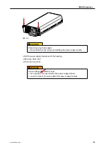
Abb. 9-7 


Place the new power supply module with the guide rails in the housing.


Slide the power supply module carefully and completely into the housing.


Take care not to cant.


Do not use any force.


Attach the power supply module with the two screws at the top.


Connect the power cable.


Turn on the new power supply module with the appropriate power switch.

The power supply module is put into operation automatically. The device is powered from 

the redundant power supply modules with equal parts of tension.

Содержание SMAVIA IPS 10000

Страница 1: ...Service English Rev 1 0 1 2018 12 19 Appliance IPS10 000...

Страница 2: ...ss negligence of the manufacturer Dallmeier electronic GmbH Co KG Bahnhofstr 16 93047 Regensburg Germany www dallmeier com info dallmeier com All trademarks identified by are registeres trademarks of...

Страница 3: ...4 9 Remote Login 11 5 Licenses 13 6 Update 14 6 10 Maintenance License 14 6 11 Implementation 15 7 Systemparameter 16 7 1 Default Parameters 16 7 2 Export Parameters 16 7 3 Import Parameters 17 8 HDD...

Страница 4: ...trained system integrators Commissioning Instructions for installation connection and commissioning for trained system integrators Service this document Instructions for maintenance and cleaning for t...

Страница 5: ...lt in minor or moderate injury NOTICE NOTICE indicates practices for preventing property damage incorrect configurations or faulty operations For reasons of clarity and readability various text format...

Страница 6: ...ernal components may cause malfunctions damages and data loss and may result in the loss of warranty Modifications Do not make any modifications to the hardware or software that have not been tested a...

Страница 7: ...horten the life of the units and may cause malfunc tions damages and data loss and may result in the loss of warranty Observe the specifications given in the technical data the operating condition req...

Страница 8: ...valid at the signing of the contract shall apply 3 6 Mainboard Battery Important basic functions eg time and hardware settings can be obtained from a battery on the main board of the appliance If the...

Страница 9: ...cumentation Commissioning It contains detailed instructions on mounting connection assignment and commissioning of the device 4 8 Local Login In order to access the configuration interface of the appl...

Страница 10: ...SMAVIA Appliance www dallmeier com 10 The configuration interface is displayed Abb 4 2 Make the required settings see below Click Close in order to exit the configuration interface...

Страница 11: ...cation Note the documentation Operation of the PService3 application Start PService3 Scan the network Select the required appliance Open the context menu with a right click Click NetConfig3 The connec...

Страница 12: ...SMAVIA Appliance www dallmeier com 12 The configuration interface is displayed Abb 4 4 Make the required settings see below Click Close in order to exit the configuration interface...

Страница 13: ...f a hardware extension in conjunction with a li cense code Open the License Code dialog via System Service Extensions Abb 5 1 Enter the license code Click OK in order to save the entry After the activ...

Страница 14: ...e licensing of the appliance An appliance is to be updated in the third year of operation with a newly released update In this case maintenance licenses for the year one free license and for the year...

Страница 15: ...iance can be triggered by an unstable power supply or via the contact IN interface Open the Software Update dialog via System Service Software Update Abb 6 2 Select the storage medium as Source Downlo...

Страница 16: ...ording settings will be lost Open the System Parameters dialog via System System Parameters Default Abb 7 1 Click OK The default system parameters will be restored 7 2 Export Parameters The system par...

Страница 17: ...t Parameters Secured or modified system parameters can be imported to restore the configuration of the SMAVIA Recording Server NOTICE Data loss System failure Inappropriate or incorrectly modified sys...

Страница 18: ...e the detailed explanations in the dialog Click Search USB stick if required Select the required storage medium as a Source Select the relevant import option Finally click OK in order to start the imp...

Страница 19: ...urpose via the infor mation dialog or via the display on the front side of the appliance 8 1 1 Information Dialog In the information dialog comprehensive information about the current status of the ha...

Страница 20: ...The defective hard disk drive can be replaced during operation hot swap Proceed as described below to ensure the highest possible data security Note that new HDDs must be tested and released for mount...

Страница 21: ...ining hard disk drives Identify the defective hard disk drive XXX Abb 8 3 Replace the defective hard disk drive see below The new hard disk drive is used as the spare hard disk drive SSS The recovery...

Страница 22: ...nd damage to property observe the proce dure described above Identify the defective hard disk drive as described above Abb 8 5 Unlock the HDD drawer unit with the key Abb 8 6 Pull the HDD drawer unit...

Страница 23: ...drawer unit Make sure that the connections of the hard disk drive are positioned on the back of the HDD drawer unit Mount the hard disk drive with the 4 screws NOTICE Possibility of data loss Always r...

Страница 24: ...drawer unit carefully and completely into the housing Make sure not to cant Do not use any force Abb 8 10 Make sure the HDD drawer unit and the housing are flush Lock the HDD drawer unit with the key...

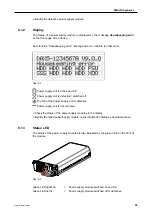
Страница 25: ...two power supply modules 9 1 Identify In the case of service the faulty power supply module must be identified first This includes three available options via the information dialog via the display o...

Страница 26: ...nd OK Power supply unit is defective switched off The fan of the power supply unit is defective Power supply unit is not mounted Check the status of the power supply modules in the display Identify th...

Страница 27: ...eactivate the defective power supply module if required Confirm with OK The display of the corresponding system message is suppressed After replacing the pow er supply module this function is activate...

Страница 28: ...removing and installing the power supply module Pull the power supply module out of the housing Take care not to cant Do not use any force WARNING Serious danger by electric shock Do not grip to the...

Страница 29: ...ly into the housing Take care not to cant Do not use any force Attach the power supply module with the two screws at the top Connect the power cable Turn on the new power supply module with the approp...

Страница 30: ...y units Ensure that both supply lines are disconnected from the supply circuit CAUTION Danger of explosion if battery is incorrectly replaced Replace and discard the battery of the main board in accor...

Отзывы: