background image

Troubleshooting

15

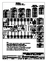
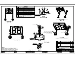
DWG-3438261

 and 

DWG-3438262

 in 

Appendix A

 indicate the driver connectors 

controlling the digits. The numbers shown in the upper half of a digit indicate which driver 

connector is wired to it. 

LED Driver

Reference Drawings:

Specifications; LED Driver IV, 16 Col

 .................................................................

DWG-288137

Specifications; Gyrus LED Driver, 16 Col

 .........................................................

DWG-3071833

Schematic; Battery Operated TI-XXXX w/Horn 

(prior to June 2016)

 ...........

DWG-3074676

Schematic; Battery Operated TI-XXXX with Horn ..........................................

DWG-3333212

Component Location; TI-2203 .........................................................................

DWG-3438261

Component Location; TI-2215 .........................................................................

DWG-3438262

The LED driver performs the task of switching digits on and off within the display. LED 

drivers are located inside of a driver enclosure. Refer to 

DWG-3438261

 and 

DWG-3438262


to view the location of the driver enclosure. Refer to 

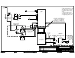
DWG-3333212

 for detailed wiring 

schematics. 

Note: 

For displays built before June 2016, refer to 

DWG-3074676

 for wiring schematics. 

When troubleshooting driver problems, several LEDs provide diagnostic information. The 

number of LEDs and their function depends on the driver type. 

Note: 

While it is necessary to have the display powered on to check the LED indicators, 

always turn off display power before servicing.

16-Column "Gyrus" Drivers

LED

Function

Operation

Summary

DS1

Radio/

RS-232 RX

Blinking 

or off

DS1 will be blinking when the driver is receiving radio 

signal and off when there is no signal.

DS2

Status

Blinking

DS2 will be blinking at one second intervals to indicate 

the driver is running.

DS5

Signal RX

Blinking 

or off

DS5 will be blinking when the driver is receiving current 

loop signal and off when there is no signal.

DS8

Power

Steady on

DS8 will be on and steady to indicate driver has power.

For detailed descriptions and pin-outs of the driver jacks, refer to 

DWG-3071833

16-Column Drivers (prior to April 2015)

LED

Function

Operation

Summary

DS1

Radio/

RS-232 RX

Blinking 

or off

DS1 will be blinking when the driver is receiving radio 

signal and off when there is no signal.

DS2

Status

Blinking

DS2 will be blinking at one second intervals to indicate 

the driver is running.

DS5

Signal RX

Blinking 

or off

DS5 will be blinking when the driver is receiving current 

loop signal and off when there is no signal.

DS8

Power

Steady on

DS8 will be on and steady to indicate driver has power.

For detailed descriptions and pin-outs of the driver jacks, refer to 

DWG-288137

Содержание P1753

Страница 1: ...201 Daktronics Drive Brookings SD 57006 5128 www daktronics com support 800 325 8766 LED TIMER W BATTERIES DISPLAY MANUAL P1192 P1753 DD2959933 Rev 10 03 August 2021...

Страница 2: ...o part of this book covered by the copyrights hereon may be reproduced or copied in any form or by any means graphic electronic or mechanical including photocopying taping or information storage and r...

Страница 3: ...ger Troubleshooting Table 9 Radio Interference 10 Battery and Charging Safety 10 Personal Safety Precautions 10 DC Connection Precautions 11 6 Troubleshooting 12 Troubleshooting Table 12 Component Loc...

Страница 4: ...This page intentionally left blank...

Страница 5: ...and void Do not drop the control equipment or allow it to get wet Specifications Label Power specifications as well as serial and model number information can be found on an ID label on the display si...

Страница 6: ...lay is controlled via an All Sport 1600 or 5000 series control console Either console may be equipped with an optional radio transmitter The controllers use keyboard overlays sport inserts to control...

Страница 7: ...8 D 711 mm 1 02 m 203 mm With Side Stands 2 4 H x 3 6 W x 16 D 711 mm 1 07 m 406 mm With Optional Cart minimized 3 6 H x 4 4 W x 2 6 D 1 07 m 1 32 m 762 mm With Optional Cart maximized 5 8 H x 4 4 W x...

Страница 8: ...e likelihood of tipping over and causing injury or damage to the display DWG 3220250 in Appendix A shows the two axle positions that may be used with the cart The extended axle position provides maxim...

Страница 9: ...nd damage the batteries Keep the display plugged in to a 120 VAC power source during storage Battery life is enhanced by keeping the batteries fully charged Typically batteries will be fully charged i...

Страница 10: ...there are other displays in the facility operating with radio signal each display receiver must be set to a different channel number typically starting with 1 and numbering consecutively Refer to DWG...

Страница 11: ...model 2607 which varies from the details provided below For more information visit www marinco com en 2607a Charger Power Specifications Outputs two individual isolated outputs with a combined rating...

Страница 12: ...let Red and green LED indicators on the charger visible through holes on the rear of the display cabinet indicate the recharging status A label at this location also describes charging levels Note Whe...

Страница 13: ...harger has overheated due to poor air circulation and has reduced its output Consider moving the display to a shaded location Red LED stays on for more than 24 hours One or more defective or damaged c...

Страница 14: ...to correct the interference with one or more of the following measures Reorient or relocate the receiving antenna Increase the separation between the equipment and the receiver Connect the equipment...

Страница 15: ...D ACID batteries only It is not intended to recharge common dry cell batteries which may burst and cause injury to people and damage to property NEVER charge a frozen battery DC Connection Precautions...

Страница 16: ...play digits do not light but console works No wired signal from control console Check that the display is receiving 120 VAC or battery power Verify the red DS5 or DS2 LED on the driver lights up when...

Страница 17: ...circuit Exchange the digit with a working one of the same part to verify the problem Replace if necessary See Replacing Digit Segments p 14 Display works but some LEDs do not light or they blink Bad...

Страница 18: ...mounted to the back of the digit panel Figure 6 Do not attempt to remove individual LEDs it may be possible to make repairs by removing just the defective segment To replace a digit segment 1 Open the...

Страница 19: ...sary to have the display powered on to check the LED indicators always turn off display power before servicing 16 Column Gyrus Drivers LED Function Operation Summary DS1 Radio RS 232 RX Blinking or of...

Страница 20: ...Drawings Address Table Rotary Switches H and L DWG 1198765 Since the same LED drivers can be used for many display models each driver must be set to receive the correct signal input or address for the...

Страница 21: ...retailer Horn TI 2015 TI 2215 A 12 V buzzer horn is mounted in the center of the front face panel of the TI 2015 TI 2215 To replace a horn 1 Open the front panel as described in Component Locations a...

Страница 22: ...s tube F 1031 Fuse MDL 1 1 A 250 V glass tube F 1077 Washer 1 2 flat prior to June 2016 HC 1095 Wheel Bolt 1 2 13 x 3 1 2 prior to June 2016 HC 1363 Washer 5 8 flat HC 1846 Wheel Bolt 5 8 11 x 4 HC 32...

Страница 23: ...__________________________ Daktronics Customer ID Number ______________________________________________________ To participate in the Exchange Program follow these steps 1 Call Daktronics Customer Ser...

Страница 24: ...nt damage during shipment Electronic components such as printed circuit boards should be placed in an antistatic bag before boxing Daktronics does not recommend using packing peanuts when shipping 4 E...

Страница 25: ...ol DWG 288137 Installation Drawing Outdoor Scbd Gen VI Radio Receiver DWG 1109181 Assy TI 2015 w Stands prior to June 2016 DWG 1200521 Specifications Gyrus LED Driver 16 Col DWG 3071833 Schematic Batt...

Страница 26: ...This page intentionally left blank...

Страница 27: ...BSIDIARIES COPYRIGHT 2021 DAKTRONICS INC USA THIRD ANGLE PROJECTION AH REV TITLE PROJECT INCHES MILLIMETERS DESIGN SCALE DIM UNITS DATE SHEET DO NOT SCALE DRAWING FUNC TYPE SIZE DRAWN JOB NO BASKETBAL...

Страница 28: ......

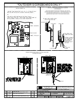
Страница 29: ...DISPLAY OR OPEN RADIO CASE BY REMOVING 4 PHILIPS HEAD SCREWS ALWAYS LEAVE FUNCTION 1 BUT CHANGE THE CHANNEL AND BCAST DIALS AS NEEDED USE SMALL FLAT HEAD SCREW DRIVER GREEN POWER LED RED DATA LED AMB...

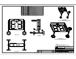
Страница 30: ...X NAME QTY DESCRIPTION 1 HC 1057 8 BOLT 3 8 16X1 HEX HEAD PLATED GRADE 5 2 HC 1087 8 NUT 3 8 16 HEX ZN PLTD GRADE 5 3 HC 1093 8 WASHER 3 8 FLAT ZN PLTD SAE 4 HC 1100 8 WASHER 3 8 SPLIT LOCK ZN PLTD ME...

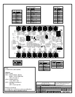
Страница 31: ...L_IN_1 N 3 LEGACY_232_IN P 4 CL_OUT P 5 CL_OUT N 6 LEGACY_AC_IN1 7 GND 8 CHGND 9 LEGACY_AC_IN2 10 GND 11 VUNREG_1_IN 12 VUNREG_2_IN THE CONCEPTS EXPRESSED AND DETAILS SHOWN ON THIS DRAWING ARE CONFIDE...

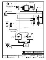
Страница 32: ...RED BLK RED RED RED RED BLK CONDUCTORS SUPPLIED WITH BATTERY CHARGER A1 LED DRIVER 1 2 1 2 4 3 REAR VIEW OF S 1076 F3 REPLACE WITH F 1031 A2 HORN CARD DC 2 1 J2 3 2 4 1 J1 PWR IN J3 PWR OUT GND P41 P...

Страница 33: ...03 10 AUG 17 PER CN 40670 ADDED ED 3695776 FOR ASSEMBLY DETAILS REPLACED HC 1846 WASHERS AND HC 3223756 BOLTS WITH HC 1273 NUTS AND HC 1579 BOLTS FLIPPED WHEELS KDD FRONT VIEW REFERENCE ED 3695776 FOR...

Страница 34: ...GRN GRN J41 POWER INLET T 1066 4 07 8016 CSA J5 1 9 2 3 4 5 6 7 8 WHT RED BLK 1 2 3 4 1 2 3 4 P2 J2 A2 HORN CARD 0P 1192 0398 1 2 1 2 1 2 1 2 J3 P3 J1 P1 RED BLK P2 1 2 P18 1 4 2 3 P5 1 9 2 3 4 5 6 7...

Страница 35: ...C 10 AMP BATTERY CHARGER STATUS LIGHTS LOCATED ON REAR OF DISPLAY 12V BATTERY FRONT VIEW SHOWN WITHOUT DIGITS OPTIONAL RADIO RIGHT SIDE OPTIONAL RADIO REV DATE BY 01 04 NOV 16 MJR PER EC 22891 ADDED H...

Страница 36: ...7 AUG 16 P1753 E 10 A 1 10 KDRAGT 3438262 04 FRONT VIEW LEFT SIDE 2 18 DRIVER CONNECTOR WIRED TO THAT DIGIT DIGIT SIZE A1 DRIVER NUMBER NOTES A1 1 A1 2 A1 24 24 OPTIONAL RADIO TI 2215 R A A1 POWER IN...

Страница 37: ...ATTERY OPERATED TI XXXX W HORN DATE 27 OCT 20 DIM UNITS INCHES MILLIMETERS SHEET REV SCALE 1 3 DO NOT SCALE DRAWING 00 DESIGN KSCHNABEL JOB NO FUNC TYPE SIZE 4764373 DRAWN KSCHNABEL P1782 E 10 B ASSEM...

Страница 38: ...This page intentionally left blank...

Страница 39: ...Daktronics Warranty Limitation of Liability 35 B Daktronics Warranty Limitation of Liability This section includes the Daktronics Warranty Limitation of Liability statement SL 02374...

Страница 40: ...This page intentionally left blank...

Страница 41: ...y per Incoterms 2020 otherwise End User shall pay transportation charges to return the Equipment back to the End User and such Equipment shall be shipped Ex Works Daktronics designated facility per In...

Страница 42: ...Daktronics or M paint or refinishing the Equipment or furnishing material for this purpose 3 Limitation of Liability A Daktronics shall be under no obligation to furnish continued service under this W...

Страница 43: ...ation of this warranty Alternatively an Extended Service Agreement may be purchased in conjunction with this Warranty for extended additional services For further information contact Daktronics Custom...

Страница 44: ...This page intentionally left blank...

Отзывы: