SiME332106E
Names and Functions
Part 3 Remote Controller
31
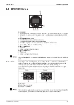
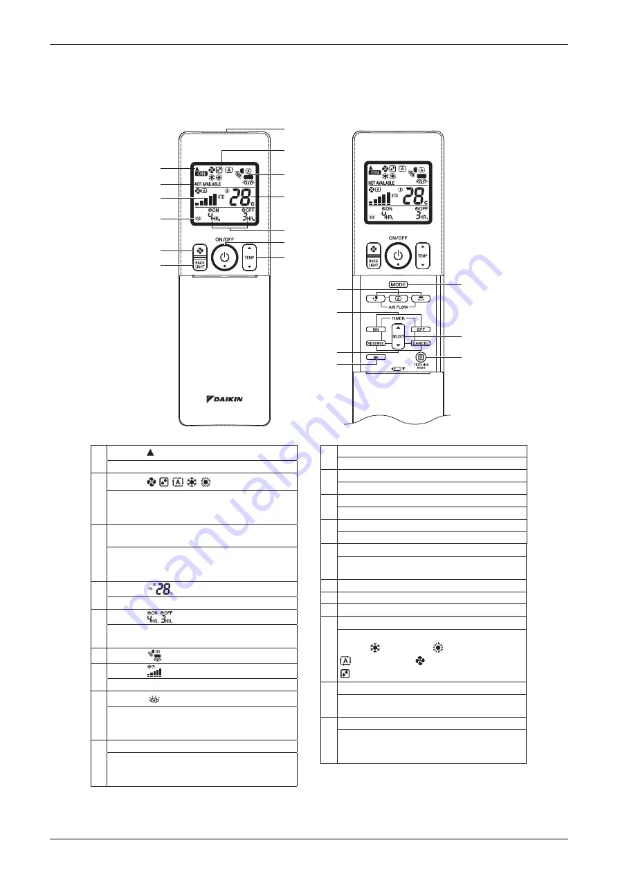
2.3 BRC4M Series
2.3.1 Remote Controller
14
18
17
11
1
3
7
8
10
12
9
5
4
6
2
13
15
16
20
19
1
DISPLAY (SIGNAL TRANSMISSION)
This blinks when a signal is being transmitted.
2
DISPLAY (OPERATION MODE)
3
4
5
This display shows the current OPERATION
MODE. Operation modes supported depend
on the model that is connected.
DISPLAY NOT AVAILABLE (displayed when
operation is not supported)
When a button for a function that is not
supported on the connected model is pressed,
this displays for 2 seconds.
DISPLAY (SET TEMPERATURE)
This display shows the set temperature.
DISPLAY (PROGRAMMED TIME)
This display shows PROGRAMMED TIME of
the air conditioner start or stop.
6
7
8
9
ON/OFF BUTTON
DISPLAY (AIRFLOW BLADE)
DISPLAY (FAN SPEED)
The display shows the set fan speed.
DISPLAY (INSPECTION)
When the INSPECTION BUTTON is pressed,
the display shows the system mode is in.
Do not operate this button during normal use.
Press the button and the air conditioner will
start. Press the button again and the air
conditioner will stop.
14
PROGRAMMING TIMER BUTTON
15 TIMER MODE ON/OFF BUTTON
16 TIMER RESERVE/CANCEL BUTTON
17 AIRFLOW DIRECTION ADJUST BUTTON
18
OPERATION MODE SELECTOR BUTTON
19
FILTER SIGN RESET BUTTON
20
INSPECTION BUTTON
Use this button for programming “START and/
or STOP” time.
Press this button to select OPERATION
MODE. (COOLING), (HEATING),
(AUTOMATIC), (FAN),
(PROGRAM DRY).
Refer to the section of MAINTENANCE in the
operation manual attached to the indoor unit.
This button is used only by qualified service
persons for maintenance purposes.
Do not operate this button during normal use.
10
FAN SPEED CONTROL BUTTON
Press this button to select the fan speed.
11
TEMPERATURE SETTING BUTTON
Use this button for SETTING TEMPERATURE.
12
BACKLIGHT BUTTON
Press this button to turn the backlight on or off.
13
SIGNAL TRANSMITTER
This sends the signals to the indoor unit.
Содержание VRV RXYMQ-A Series
Страница 1: ...Service Manual RXYMQ A Series Heat Pump 50 60 Hz SiME332106E...
Страница 283: ...SiME332106E Check Part 6 Service Diagnosis 277 PCB and Circuit Diagram U V W L3B L2B L1B P1 P2 N32...
Страница 296: ...SiME332106E 290 Part 7 Appendix 1 Wiring Diagrams 291 1 1 Outdoor Unit 291 1 2 VRV Indoor Unit 293 Part 7 Appendix...
Страница 297: ...SiME332106E Wiring Diagrams Part 7 Appendix 291 1 Wiring Diagrams 1 1 Outdoor Unit RXYMQ4AVMK C 3D133942...
Страница 298: ...Wiring Diagrams SiME332106E 292 Part 7 Appendix RXYMQ4 5 6AYFK C 3D133944A...
Страница 303: ...SiME332106E Wiring Diagrams Part 7 Appendix 297 FXMQ40 50 63 80 100ARV1 3D127112 04 59...


