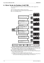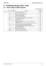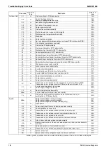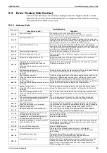
Servicing Items to be Confirmed
SiME332106E
142
Part 6 Service Diagnosis
1. Servicing Items to be Confirmed
1.1 Troubleshooting
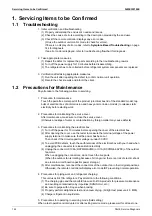
1. Initial verification and troubleshooting
(1) Properly understand the end user's needs and issues.
(2) Check the cause of errors according to the description provided by the end user.
(3) Check if the remote controller displays any error codes.
(Or use the outdoor unit monitor mode to check for errors).
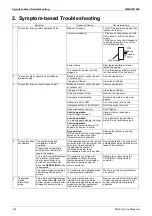
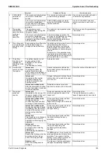
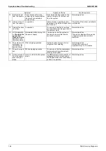
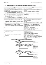
If there is no display of error codes, refer to
Symptom-Based Troubleshooting
on page
144 for diagnosis.
If an error code is displayed, refer to troubleshooting flowchart for diagnosis.
2. Take appropriate measures.
(1) Repair the defect or replace the parts according to the troubleshooting results.
(2) Turn off the power supply for 10 minutes before disassembling.
(3) The refrigerant has to be collected before refrigerant system components are replaced.
3. Verification after taking appropriate measures
(1) Run the unit after repairing the defect to confirm normal unit operation.
(2) Record the check results and inform the client.
1.2 Precautions for Maintenance
Pay attention to the following matters in servicing.
1. Precaution for maintenance
Touch the paint-free metal part of the product (electrical box lid of the standard model; tap
bolts of electrical box of anti-corrosion and heavy anti-corrosion models) to release static
electricity before starting work.
2. Precautions for maintaining the service cover
After maintenance, make sure to close the service cover.
(Otherwise, leakage of water or contamination by foreign matter may cause defects)
3. Precautions for maintaining the electrical box
(1) Turn off the power for 10 minutes before opening the cover of the electrical box.
(2) After opening the cover, use the tester to measure the terminal voltage of the power
supply terminal to make sure that the power has been cut.
Then check if the circuit capacitor voltage is under 50 VDC.
(3) To avoid PCB defects, touch the earth terminal of the electrical box with your hand when
unplugging the connector to release static electricity.
(4) Unplug the connector X106A (RXYMQ4AVMK) or X1A (RXYMQ4-6AYFK) of the outdoor
fan motor.
When unplugging the connectors, do not touch the live parts.
(When the outdoor fan is rotating because of strong wind, there is a risk of electric shock
due to main circuit board capacitor power storage.)
(5) After maintenance, reconnect the connectors of the outdoor fan in their original positions.
Otherwise, the remote controller will display error code
E7
, preventing normal operation.
4. Precautions for piping work and refrigerant charging:
This unit uses R-410A refrigerant. Pay attention to the following conditions.
(1) The charging pipe and the manifold tube use R-410A products for pressure maintenance
and avoiding contamination by impurities (SUNISO oil, etc.).
(2) Be sure to purge with nitrogen when brazing.
(3) Properly perform airtightness test and vacuum drying. (Airtight test pressure: 4.0 MPa)
(4) Charge refrigerant in liquid state.
5. Precautions for operating in servicing mode (field setting):
When a test operation is interrupted or after exiting service mode, please wait for at least one
Содержание VRV RXYMQ-A Series
Страница 1: ...Service Manual RXYMQ A Series Heat Pump 50 60 Hz SiME332106E...
Страница 283: ...SiME332106E Check Part 6 Service Diagnosis 277 PCB and Circuit Diagram U V W L3B L2B L1B P1 P2 N32...
Страница 296: ...SiME332106E 290 Part 7 Appendix 1 Wiring Diagrams 291 1 1 Outdoor Unit 291 1 2 VRV Indoor Unit 293 Part 7 Appendix...
Страница 297: ...SiME332106E Wiring Diagrams Part 7 Appendix 291 1 Wiring Diagrams 1 1 Outdoor Unit RXYMQ4AVMK C 3D133942...
Страница 298: ...Wiring Diagrams SiME332106E 292 Part 7 Appendix RXYMQ4 5 6AYFK C 3D133944A...
Страница 303: ...SiME332106E Wiring Diagrams Part 7 Appendix 297 FXMQ40 50 63 80 100ARV1 3D127112 04 59...

