Test Operation
SiME332106E
136
Part 5 Field Settings and Test Operation
Warning
3.3 Test Operation Procedure
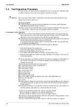
To start smoothly, a crankcase heater is equipped to the unit. To power up the crankcase heater
in advance, be sure to turn on the power supply 6 hours before operation.
Be sure to inform other installers or attach the front panel well before leaving with the power
supply turned on for the outdoor unit.
Before powering ON
Protect the electronic components with insulating tape in accordance with the
Service
Precautions
label attached to the front panel.
All indoor units connected with the outdoor unit will operate automatically after powering on.
To ensure safety, check the indoor unit installation has been completed.
Powering On to Test Operation
Make sure to perform a test operation first after installation (If the unit is operated with the
indoor unit’s remote controller without performing a test operation, the error code
U3
will be
displayed on the remote controller and the unit will not operate normally).
After turning on the power supply, do not touch any switches excluding push button switches
and DIP switches when setting the outdoor unit PCB (A1P).
(For positions of the button switches (BS1~3) and DIP switches (DS1, 2) on the PCB, refer
to the
Service Precautions
label)
Check the state of the outdoor units and fault wiring with this operation.
1. Attach the front panel of the outdoor unit.
Turn on the power supply of the outdoor and indoor units.
2. Make sure all field settings you want are set.
3. Turn ON the power to the outdoor unit and the connected indoor units.
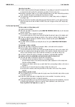
4. Make sure the default (idle) situation is existing. Push BS2 for 5 seconds or more. The unit
will start test operation.
The test operation is automatically carried out, the outdoor unit display will indicate
t01
and
the indication "Test operation" and "Under centralized control" will display on the user
interface of indoor units.
Steps during the automatic system test run procedure:
t01
: control before start up (pressure equalization)
t02
: cooling start up control
t03
: cooling stable condition
t04
: communication check
t05
: stop valve check
t06
: pipe length check
t07
: refrigerant amount check
t08
: in case [2-88]=0, detailed refrigerant situation check (RXYMQ4AVMK only)
t09
: pump down operation
t10
: unit stop
If the automatic refrigerant charge function has been used,
t07
and
t08
will not be displayed
during the test operation, as they have already been checked during automatic refrigerant
charge operation.
During the test operation, it is not possible to stop the unit operation from a user interface. To
abort the operation, press BS3. The unit will stop after ±30 seconds.
5. Check the test operation results on the outdoor unit segment display.
Normal completion: no indication on the segment display (idle)
Abnormal completion: indication of error code on the segment display
Take actions for correcting the abnormality. When the test operation is fully completed, normal
operation will be possible after 5 minutes.
6. Be sure to attach the front panel of the outdoor unit after test operation is completed.
Содержание VRV RXYMQ-A Series
Страница 1: ...Service Manual RXYMQ A Series Heat Pump 50 60 Hz SiME332106E...
Страница 283: ...SiME332106E Check Part 6 Service Diagnosis 277 PCB and Circuit Diagram U V W L3B L2B L1B P1 P2 N32...
Страница 296: ...SiME332106E 290 Part 7 Appendix 1 Wiring Diagrams 291 1 1 Outdoor Unit 291 1 2 VRV Indoor Unit 293 Part 7 Appendix...
Страница 297: ...SiME332106E Wiring Diagrams Part 7 Appendix 291 1 Wiring Diagrams 1 1 Outdoor Unit RXYMQ4AVMK C 3D133942...
Страница 298: ...Wiring Diagrams SiME332106E 292 Part 7 Appendix RXYMQ4 5 6AYFK C 3D133944A...
Страница 303: ...SiME332106E Wiring Diagrams Part 7 Appendix 297 FXMQ40 50 63 80 100ARV1 3D127112 04 59...

