SiME332106E
Field Settings for Outdoor Unit
Part 5 Field Settings and Test Operation
109
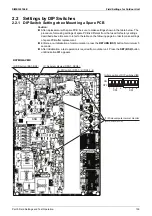
2.2 Settings by DIP Switches
2.2.1 DIP Switch Setting when Mounting a Spare PCB
Caution:
After replacement with spare PCB, be sure to make settings shown in the table below. The
procedure for making settings of spare PCB is different from that used for factory settings
described above. Be sure to refer to the table on the following page in order to make settings
of spare PCB after replacement.
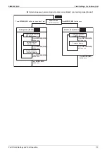
Enforce a re-initialization of communication: press the
RETURN (BS3)
button for minimum 5
seconds.
After initialization, a test operation is required from outdoor unit. Press the
SET (BS2)
button
until indication
t01
appears.
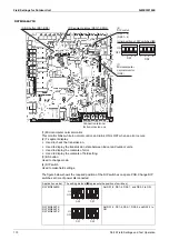
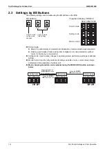
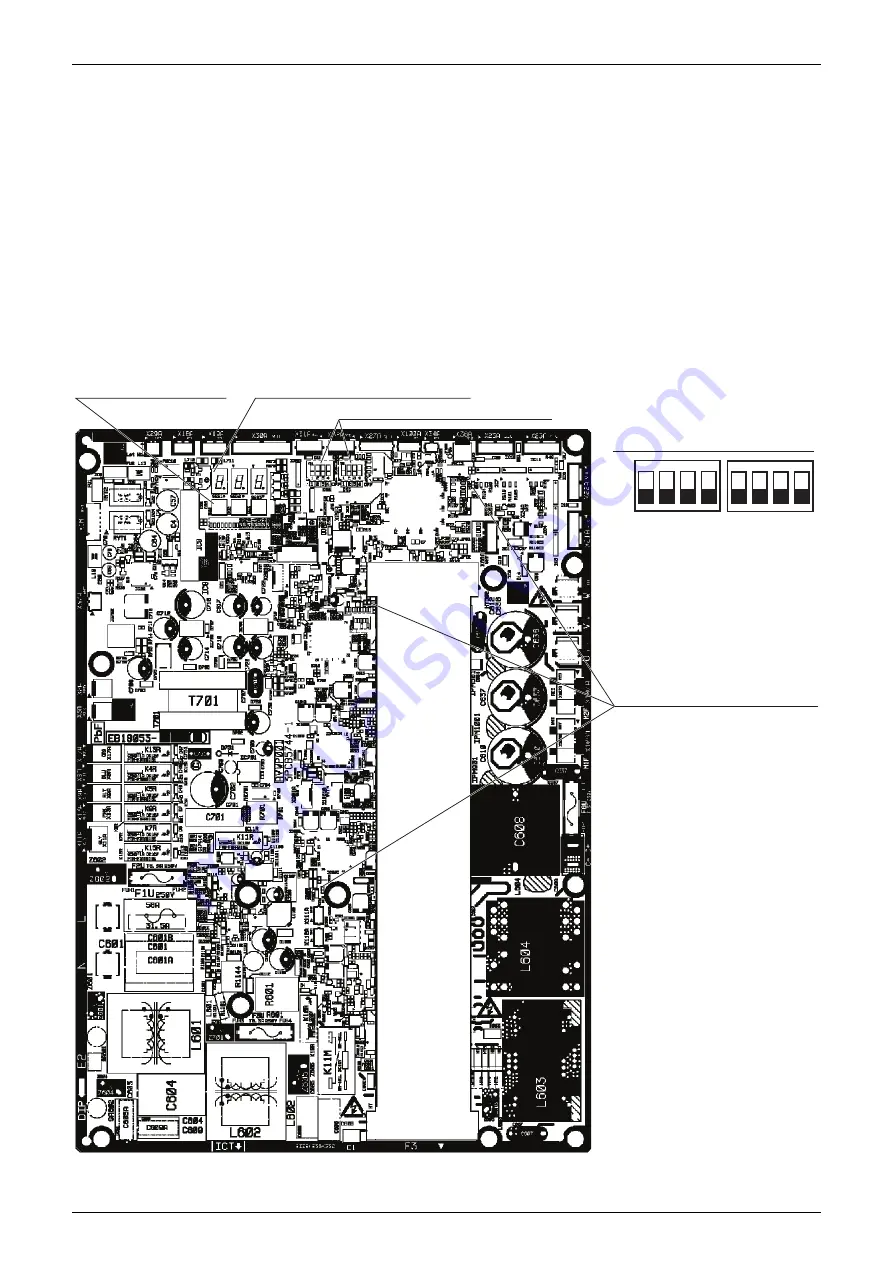
RXYMQ4AVMK
(3) BS button (BS1~BS3)
(2) Segment display (SEG1~SEG3)
(4) DIP switch (DS1-1~4) (DS2-1~4)
ON
OFF
1
2
3
4
DS2
Initial position of DIP switches (
)
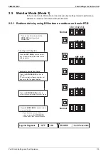
(1) Microcomputer normal monitor
(HAP, HBP, HCP)
1
2
3
4
DS1
Содержание VRV RXYMQ-A Series
Страница 1: ...Service Manual RXYMQ A Series Heat Pump 50 60 Hz SiME332106E...
Страница 283: ...SiME332106E Check Part 6 Service Diagnosis 277 PCB and Circuit Diagram U V W L3B L2B L1B P1 P2 N32...
Страница 296: ...SiME332106E 290 Part 7 Appendix 1 Wiring Diagrams 291 1 1 Outdoor Unit 291 1 2 VRV Indoor Unit 293 Part 7 Appendix...
Страница 297: ...SiME332106E Wiring Diagrams Part 7 Appendix 291 1 Wiring Diagrams 1 1 Outdoor Unit RXYMQ4AVMK C 3D133942...
Страница 298: ...Wiring Diagrams SiME332106E 292 Part 7 Appendix RXYMQ4 5 6AYFK C 3D133944A...
Страница 303: ...SiME332106E Wiring Diagrams Part 7 Appendix 297 FXMQ40 50 63 80 100ARV1 3D127112 04 59...

