SiME332106E
Field Settings for Indoor Unit
Part 5 Field Settings and Test Operation
101
Note(s)
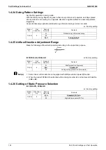
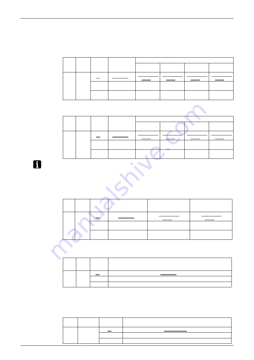
1.4.22 Ceiling Height Setting, Setting of Normal Airflow
Make the following setting according to the ceiling height.
FXFSQ25-80AR
: Factory setting
FXFSQ100-140AR
: Factory setting
1. The Second Code No. is factory set to Standard/All-direction airflow. For High ceiling (1) or
(2), initial setting by remote controller is required.
2. A closing member kit (optional) is required for 4-, 3-, or 2-direction airflow.
FXFSQ-AR with Designer panel
: Factory setting
FXAQ-AR
: Factory setting
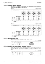
1.4.23 Airflow Direction Setting
Set the airflow direction of indoor units as given in the table below. (Set when sealing material
kit of air discharge outlet has been installed.) The second code No. is factory set to
01
.
: Factory setting
Mode
No.
First
Code
No.
Second
Code
No.
Contents
Ceiling Height
All round
outlet
4-way
Outlets
3-way
Outlets
2-way
Outlets
13
(23)
0
01
Standard
Lower than
2.7 m
Lower than
3.1 m
Lower than
3.0 m
Lower than
3.5 m
02
High Ceiling
Lower than
3.0 m
Lower than
3.4 m
Lower than
3.3 m
Lower than
3.8 m
03
Higher Ceiling
Lower than
3.5 m
Lower than
4.0 m
Lower than
3.5 m
—
Mode
No.
First
Code
No.
Second
Code
No.
Contents
Ceiling Height
All round
outlet
4-way
Outlets
3-way
Outlets
2-way
Outlets
13
(23)
0
01
Standard
Lower than
3.2 m
Lower than
3.4 m
Lower than
3.6 m
Lower than
4.2 m
02
High Ceiling
Lower than
3.6 m
Lower than
3.9 m
Lower than
4.0 m
Lower than
4.2 m
03
Higher Ceiling
Lower than
4.2 m
Lower than
4.5 m
Lower than
4.2 m
—
Mode
No.
First
Code
No.
Second
Code No.
Contents
FXFSQ25-80AR
(All round outlet)
FXFSQ100-140AR
(All round outlet)
13
(23)
0
01
Standard
Lower than
2.4 m
Lower than
3.2 m
02
High Ceiling (1)
Lower than
2.7 m
Lower than
3.6 m
03
High Ceiling (2)
Lower than
3.2 m
Lower than
4.2 m
Mode
No.
First
Code
No.
Second
Code No.
Contents
13
(23)
0
01
Standard
02
Slightly higher
03
High
Mode
No.
First
Code No.
Second
Code No.
Contents
13 (23)
1
01
4-way airflow
02
3-way airflow
03
2-way airflow
Содержание VRV RXYMQ-A Series
Страница 1: ...Service Manual RXYMQ A Series Heat Pump 50 60 Hz SiME332106E...
Страница 283: ...SiME332106E Check Part 6 Service Diagnosis 277 PCB and Circuit Diagram U V W L3B L2B L1B P1 P2 N32...
Страница 296: ...SiME332106E 290 Part 7 Appendix 1 Wiring Diagrams 291 1 1 Outdoor Unit 291 1 2 VRV Indoor Unit 293 Part 7 Appendix...
Страница 297: ...SiME332106E Wiring Diagrams Part 7 Appendix 291 1 Wiring Diagrams 1 1 Outdoor Unit RXYMQ4AVMK C 3D133942...
Страница 298: ...Wiring Diagrams SiME332106E 292 Part 7 Appendix RXYMQ4 5 6AYFK C 3D133944A...
Страница 303: ...SiME332106E Wiring Diagrams Part 7 Appendix 297 FXMQ40 50 63 80 100ARV1 3D127112 04 59...

