


Si37-701
Outline of Control (Indoor Unit)
Function
133
6. Outline of Control (Indoor Unit)
6.1
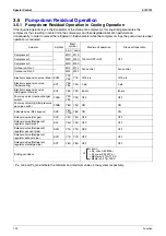
Operation Flow Chart
Start
Heating Operation
Fan Operation
Cooling Operation
Turn ON
power supply
Cooling Operation
LED in remote
controller turns ON
Drain
pump kit
Aux. electric
heater
Detect louver lock
( )
Run or Stop?
RUN indicating lamp: OFF
RUN indicating lamp: Blink
Malfunction code: Displayed
RUN indicating lamp: OFF
Malfunction mode display: Reset
Is
Restart prevention
operation in progress?
(5 min.)
Is
freeze prevention
operation in progress?
Is
test run
in progress?
Thermostat status
Fan or Temp.
control?
Cooling or
Heating?
Swing flap
Dew
prevention condition?
Swing flap
Set wind direction
Dew prevention position
Cassette type: P1
Ceiling suspended type: P0
Microcomputer dry
ON/OFF
Microcomputer dry display:
Reset
Microcomputer dry operation
Fan:
Operating with set air flow rate
A
A
A
Stop
Run
Yes
Yes
Yes
Yes
Yes
Yes
No
No
No
No
ON
OFF
No
No
No
Cyclic operation with
RUN/STOP pushbutton
*1
Fan
Temp. control
Heating
Cooling
*2 Fan : Stop
Louver : Stop
*3
*6
*5
*4
(Option)
(Option)
(Option)
(Option)
(Option)
(Option)
OFF
ON
MF
MF
: OFF
MP
Drain pump kit
: OFF after 5-min.
residual operation
MP
Drain pump kit
: OFF after 5-min.
residual operation
MP
Drain pump kit
:ON
MP
Drain pump kit
: ON
MP
: Closed
20E
Electronic expansion valve
: Capacity control
20E
Electronic expansion valve
: Closed
20E
MA
: OFF
52H
Aux. electric
heater
: OFF
52H
Humidifier : OFF
Mu
Humidifier : OFF
Mu
OFF
ON
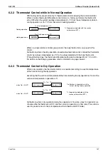
a
b
Set temperature
Suction air temperature
a=b=1
(a=b=0.5 is only available for the FXCQ, FXFQ, FXHQ, and FXKQ series.)
20E
Initialize electronic
expansion valve
The previous settings of air
flow rate, wind direction, and
temperature are displayed.
Is the
safety device
activated?
Is the RUN
indicating lamp
blinking?
Press the RESET
RUN/STOP
pushbutton.
Electronic
expansion valve
Thermostat-ON-
operation signal to
outdoor unit: Output
Thermostat-ON-
operation signal to
outdoor unit: Output
*1. If any malfunction occurs, the relevant malfunction code will be displayed according to the malfunction
code display of the remote controller.
*2. When the aux. electric heater turns ON, the fan will stop after it conducts residual operation for 1 min.
*3. When the drain pump kit turns ON, the drain pump kit will stop after it conducts residual operation for a
period of 5 min.
*4. If the evaporator inlet temperature is kept at not more than -5
°
C for a period of cumulative 10 min. or
not more than -1
°
C for a cumulative period of 40 min., frost prevention operation will be conducted. If
the evaporator inlet temperature is kept at not less than 7
°
C for a consecutive period of 10 min., the
frost prevention operation will be reset.
*5. Thermostat status
*6. The FXCQ, FXFQ, FXKQ, and FXSQ series have the drain pump as standard equipment.
RUN indicating lamp: ON
Air flow rate display: Displayed
Wind direction display: Displayed
Temp. setting display: Displayed
Содержание VRV III REYQ10PY1
Страница 1: ...REYQ8 48PY1 R 410A Heat Recovery 50Hz Si37 701 ...
Страница 59: ...Specifications Si37 701 48 Specifications ...
Страница 105: ...Refrigerant Flow for Each Operation Mode Si37 701 94 Refrigerant Circuit ...
Страница 230: ...Si37 701 Troubleshooting by Remote Controller Troubleshooting 219 ...
Страница 373: ...Piping Diagrams Si37 701 362 Appendix 1 Piping Diagrams 1 1 Outdoor Unit REYQ8P 10P 12PY1 3D058154A S1NPH S2NPL ...
Страница 374: ...Si37 701 Piping Diagrams Appendix 363 REYQ14P 16PY1 3D058153A S2NPL S1NPH ...
Страница 375: ...Piping Diagrams Si37 701 364 Appendix REMQ8PY1 3D057743 ...
Страница 376: ...Si37 701 Piping Diagrams Appendix 365 REMQ10PY1 12PY1 3D057742 ...
Страница 377: ...Piping Diagrams Si37 701 366 Appendix REMQ14PY1 16PY1 3D057741 ...
Страница 382: ...Si37 701 Piping Diagrams Appendix 371 1 3 BS Unit 4D057985A ...
Страница 384: ...Si37 701 Wiring Diagrams for Reference Appendix 373 REYQ14 16PY1 3D056774C ...
Страница 385: ...Wiring Diagrams for Reference Si37 701 374 Appendix REMQ8PY1 3D055307E ...
Страница 386: ...Si37 701 Wiring Diagrams for Reference Appendix 375 REMQ10 12PY1 3D055308E ...
Страница 387: ...Wiring Diagrams for Reference Si37 701 376 Appendix REMQ14P 16PY1 3D055309E ...
Страница 388: ...Si37 701 Wiring Diagrams for Reference Appendix 377 2 2 Field Wiring REYQ8P 10P 12P 14P 16PY1 3D057764 ...
Страница 389: ...Wiring Diagrams for Reference Si37 701 378 Appendix REYQ18P 20P 22P 24P 26P 28P 30P 32PY1 3D057762 ...
Страница 390: ...Si37 701 Wiring Diagrams for Reference Appendix 379 REYQ34P 36P 38P 40P 42P 44P 46P 48PY1 3D057763 ...
Страница 391: ...Wiring Diagrams for Reference Si37 701 380 Appendix 2 3 Indoor Unit FXCQ20M 25M 32M 63MVE 3D039556A ...
Страница 392: ...Si37 701 Wiring Diagrams for Reference Appendix 381 FXCQ40M 50M 80M 125MVE 3D039557A ...
Страница 393: ...Wiring Diagrams for Reference Si37 701 382 Appendix FXFQ25M 32M 40M 50M 63M 80M 100M 125MVE 3D039600A ...
Страница 394: ...Si37 701 Wiring Diagrams for Reference Appendix 383 FXZQ20M 25M 32M 40M 50M8V1B 3D038359 ...
Страница 395: ...Wiring Diagrams for Reference Si37 701 384 Appendix FXKQ25MA 32MA 40MA 63MAVE 3D039564C ...
Страница 399: ...Wiring Diagrams for Reference Si37 701 388 Appendix FXDYQ180M 200M 250MV1 ...
Страница 400: ...Si37 701 Wiring Diagrams for Reference Appendix 389 FXSQ20M 25M 32M 40M 50M 63M 80M 100M 125MVE 3D039561B ...
Страница 401: ...Wiring Diagrams for Reference Si37 701 390 Appendix FXMQ40MA 50MA 63MA 80MA 100MA 125MAVE 3D039620B ...
Страница 402: ...Si37 701 Wiring Diagrams for Reference Appendix 391 FXMQ200MA 250MAVE 3D039621B ...
Страница 403: ...Wiring Diagrams for Reference Si37 701 392 Appendix FXHQ32MA 63MA 100MAVE 3D039801D ...
Страница 404: ...Si37 701 Wiring Diagrams for Reference Appendix 393 FXAQ20MA 25MA 32MAVE 40MA 50MA 63MAVE 3D034206D ...
Страница 406: ...Si37 701 Wiring Diagrams for Reference Appendix 395 2 4 BS Unit 3D055928C ...
Страница 423: ...Piping Installation Point Si37 701 412 Appendix ...
Страница 427: ...Example of Connection R 410A Type Si37 701 416 Appendix ...
Страница 433: ...Method of Checking the Inverter s Power Transistors and Diode Modules Si37 701 422 Appendix ...
Страница 447: ...Si37 701 iv Index ...
Страница 451: ...Si37 701 viii Drawings Flow Charts ...


