


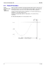
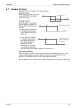


Other Control
Si39-502A
74
Function
5.
Other Control
5.1
Outdoor Unit Rotation
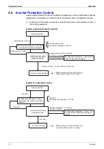
In the case of multi-outdoor-unit system, this outdoor unit rotation is used to prevent the
compressor from burning out due to unbalanced oil level between outdoor units.
[Details of outdoor unit rotation]
In the case of multi-outdoor-unit system, each outdoor unit is given an operating priority for the
control.
Outdoor unit rotation makes it possible to change the operating priority of outdoor units.
Thus, the system becomes free of compressors that stop over an extended period of time at the
time of partial loading, preventing unbalanced oil level.
[Timing of outdoor unit rotation]
• After oil return operation
• After defrosting operation
• At the beginning of the starting control
• When any of compressors stops for a period of 20 minutes or more
(in heating operation)
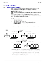
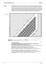
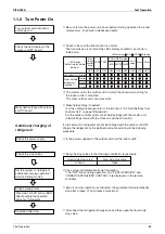
Example) The following diagram shows outdoor unit rotation in combination of 3 outdoor units.
∗
“Master unit”, “slave unit 1” and “slave unit 2” in this section are the names for installation.
They are determined in installation work, and not changed thereafter. (These names are
different from “master unit” and “slave unit” for control.)
The outdoor unit connected the control wires (F1 and F2) for the indoor unit should be
designated as master unit.
Consequently, The LED display on the main PC board for “master unit”, “slave unit 1” and
“slave unit 2” do not change. (Refer to the page 76.)
or
Normal operation
Starting
control
Outdoor unit
rotation
Oil return operation
or defrosting
operation
Priority
1
Priority
2
Priority
3
Outdoor unit
rotation
Priority
3
Priority
1
Priority
2
Normal operation
Normal operation
Outdoor unit
rotation
Priority
2
Priority
3
Priority
1
Normal operation
Priority
3
Priority
1
Priority
2
Master Slave 1 Slave 2
Master Slave 1 Slave 2
Master Slave 1 Slave 2
Master Slave 1 Slave 2
Any of
compressors stops
for a period of 20
minutes or more.
Содержание VRV II RXYQ8MY1K
Страница 18: ...Si39 502A Specifications 7 Part 2 Specifications 1 Specifications 8 1 1 Outdoor Units 8 1 2 Indoor Units 16...
Страница 53: ...Specifications Si39 502A 42 Specifications...
Страница 143: ...Field Setting Si39 502A 132 Test Operation...
Страница 247: ...Piping Diagrams Si39 502A 236 Appendix 1 Piping Diagrams 1 1 Outdoor Unit RXYQ8MY1K E YLK E RXYQ10MY1K E YLK E 3D049524...
Страница 250: ...Si39 502A Piping Diagrams Appendix 239 FXUQ BEVQ Indoor unit Connection Unit 4D037995F 4D034127B...
Страница 251: ...Piping Diagrams Si39 502A 240 Appendix FXAQ BEVQ Indoor unit Connection Unit 4D047084 4D034127B...
Страница 252: ...Si39 502A Piping Diagrams Appendix 241 FXLQ BEVQ Indoor unit Connection Unit 4D047084 4D034127B...
Страница 254: ...Si39 502A Wiring Diagrams for Reference Appendix 243 2 2 Field Wiring RXYQ8MY1K E YLK E RXYQ10MY1K E YLK E 3D040746J...
Страница 255: ...Wiring Diagrams for Reference Si39 502A 244 Appendix RXYQ16MY1K E YLK E RXYQ18MY1K E YLK E RXYQ20MY1K E YLK E 3D040747H...
Страница 257: ...Wiring Diagrams for Reference Si39 502A 246 Appendix 2 3 Indoor Unit FXCQ20M 25M 32M 63MVE 3D039556A...
Страница 258: ...Si39 502A Wiring Diagrams for Reference Appendix 247 FXCQ40M 50M 80M 125MVE 3D039557A...
Страница 259: ...Wiring Diagrams for Reference Si39 502A 248 Appendix FXFQ25M 32M 40M 50M 63M 80M 100M 125MVE 3D039600A...
Страница 260: ...Si39 502A Wiring Diagrams for Reference Appendix 249 FXKQ25M 32M 40M 63MVE 3D039564A...
Страница 261: ...Wiring Diagrams for Reference Si39 502A 250 Appendix FXDQ20N 25N 32N 40N 50N 63NVE with Drain Pump 3D045500B...
Страница 262: ...Si39 502A Wiring Diagrams for Reference Appendix 251 FXDQ20N 25N 32N 40N 50N 63NVET without Drain Pump 3D049604A...
Страница 263: ...Wiring Diagrams for Reference Si39 502A 252 Appendix FXSQ20M 25M 32M 40M 50M 63M 80M 100M 125MVE 3D039561A...
Страница 264: ...Si39 502A Wiring Diagrams for Reference Appendix 253 FXMQ40M 50M 63M 80M 100M 125MVE 3D039620A...
Страница 265: ...Wiring Diagrams for Reference Si39 502A 254 Appendix FXMQ200M 250MVE 3D039621A...
Страница 266: ...Si39 502A Wiring Diagrams for Reference Appendix 255 FXHQ32M 63M 100MVE 3D039801C...
Страница 267: ...Wiring Diagrams for Reference Si39 502A 256 Appendix FXAQ20M 25M 32M 40M 50M 63MVE 3D034206A...
Страница 269: ...Wiring Diagrams for Reference Si39 502A 258 Appendix FXUQ71M 100M 125MV1 3D044973...
Страница 270: ...Si39 502A Wiring Diagrams for Reference Appendix 259 FXAQ20MH 25MH 32MH 40MH 50MHV1 3D046348A...
Страница 271: ...Wiring Diagrams for Reference Si39 502A 260 Appendix FXLQ20MH 25MH 32MH 40MH 50MHV1 3D046787A...
Страница 272: ...Si39 502A Wiring Diagrams for Reference Appendix 261 BEVQ50MVE 3D046579A Notes...
Страница 273: ...Wiring Diagrams for Reference Si39 502A 262 Appendix BEVQ71M 100M 125MVE 3D044901A Notes...
Страница 285: ...Piping Installation Point Si39 502A 274 Appendix...
Страница 293: ...Method of Replacing The Inverter s Power Transistors and Diode Modules Si39 502A 282 Appendix...
Страница 307: ...Si39 502A iv Index...


