Test Operation
Si39-504
110
Test Operation
1.2
Operation When Power is Turned On
1.2.1 When Turning On Power First Time
The unit cannot be run for up to 12 minutes to automatically set the master power and address
(indoor-outdoor address, etc.).
Status
1.2.2 When Turning On Power The Second Time and Subsequent
Tap the RESET button on the outdoor unit PC board. Operation becomes possible for about 2
minutes. If you do not push the RESET button, the unit cannot be run for up to 10 minutes to
automatically set master power.
Status
1.2.3 When an Indoor Unit or Outdoor unit Has Been Added, or Indoor or
Outdoor Unit PC Board Has Been Changed
Be sure to push and hold the RESET button for 5 seconds. If not, the addition cannot be
recognized. In this case, the unit cannot be run for up to 12 minutes to automatically set the
address (indoor-outdoor address, etc.)
Status
Outdoor unit
Test lamp H2P .... Blinks
Can also be set during operation described above.
Indoor unit
If ON button is pushed during operation described above, the "UH"
malfunction indicator blinks.
(Returns to normal when automatic setting is complete.)
Outdoor unit
Test lamp H2P .... Blinks
Can also be set during operation described above.
Indoor unit
If ON button is pushed during operation described above, the operation lamp
lights but the compressor does not operate. (Returns to normal when
automatic setting is complete.)
Outdoor unit
Test lamp H2P .... ON
Can also be set during operation described above.
Indoor unit
If ON button is pushed during operation described above, the "UH" or "U4"
malfunction indicator blinks. (Returns to normal when automatic setting is
complete.)
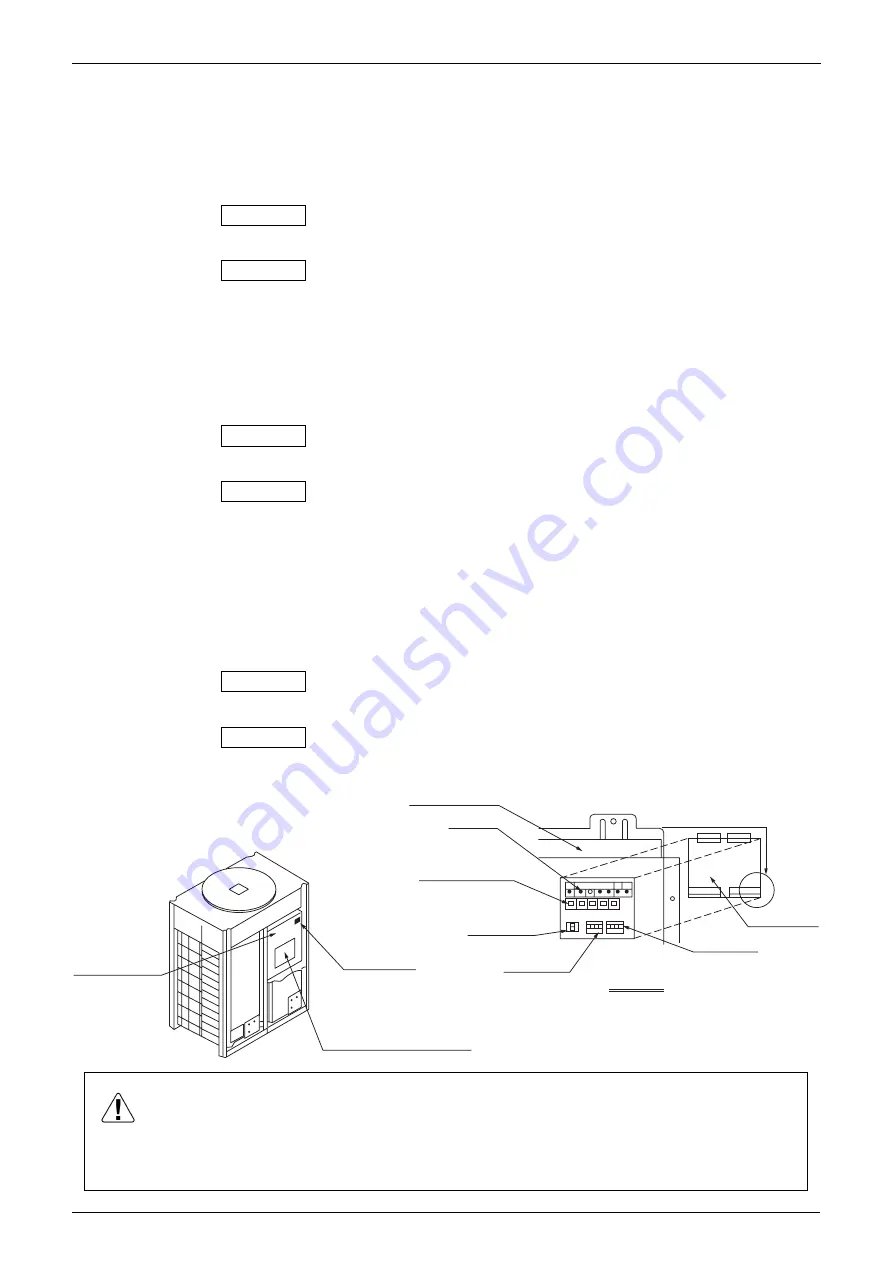
Switch box cover
Service cover
[Service Precautions] label
Switch box cover
LED
(H1~7P)
Pushbutton switch
(BS1~5)
Dip switch3
(BS3-1~2)
Dip switch1
(DS1-1~4)
Dip switch2
(DS2-1~4)
Switch box
Service cover
Lift up this protrusion
to remove the cover.
Caution When the 400 volt power supply is applyed to "N" phase by mistake,
replace Inverter P.C.B (A2P) and control transformer (T1R, T2R) in
switch box together.
(V0847)
Содержание VRV II RXYQ5MATL
Страница 20: ...Si39 504 Specifications 9 Part 2 Specifications 1 Specifications 10 1 1 Outdoor Units 10 1 2 Indoor Units 21...
Страница 53: ...Specifications Si39 504 42 Specifications...
Страница 56: ...Si39 504 Refrigerant Circuit Refirgerant Circuit 45 RXYQ5MA 3D048203 2 4 3 5 K J S E D M T N P A G O 1 W V...
Страница 115: ...Outline of Control Indoor Unit Si39 504 104 Function...
Страница 161: ...Field Setting Si39 504 150 Test Operation...
Страница 172: ...Si39 504 Troubleshooting by Remote Controller Troubleshooting 161...
Страница 265: ...Piping Diagrams Si39 504 254 Appendix 1 Piping Diagrams 1 1 Outdoor Unit RXYQ5MAYL E TL E 3D048203...
Страница 266: ...Si39 504 Piping Diagrams Appendix 255 RXYQ8MA 10MA 12MAYL E TL E 3D048033A...
Страница 267: ...Piping Diagrams Si39 504 256 Appendix RXYQ14MA 16MAYL E TL E 3D048034A...
Страница 271: ...Wiring Diagrams for Reference Si39 504 260 Appendix RXYQ8MA 10MA 12MAYL E 3D047088C...
Страница 272: ...Si39 504 Wiring Diagrams for Reference Appendix 261 RXYQ14MA 16MAYL E 3D047089C...
Страница 273: ...Wiring Diagrams for Reference Si39 504 262 Appendix 2 1 2 RXYQ MATL E RXYQ5MATL E 3D049059A...
Страница 274: ...Si39 504 Wiring Diagrams for Reference Appendix 263 RXYQ8MA 10MA 12MATL E 3D049060A...
Страница 275: ...Wiring Diagrams for Reference Si39 504 264 Appendix RXYQ14MA 16MATL E 3D049061A...
Страница 277: ...Wiring Diagrams for Reference Si39 504 266 Appendix RXYQ18MA 20MA 22MA 24MA 26MA 28MA 30MA 32MAYL E 3D040747H...
Страница 278: ...Si39 504 Wiring Diagrams for Reference Appendix 267 RXYQ34MA 36MA 38MA 40MA 42MA 44MA 46MA 48MAYL E C 3D040748H...
Страница 279: ...Wiring Diagrams for Reference Si39 504 268 Appendix 2 2 2 RXYQ MATL E RXYQ5MA 8MA 10MA 12MA 14MA 16MATL E 3D041990A...
Страница 280: ...Si39 504 Wiring Diagrams for Reference Appendix 269 RXYQ18MA 20MA 22MA 24MA 26MA 28MA 30MA 32MATL E 3D041991A...
Страница 281: ...Wiring Diagrams for Reference Si39 504 270 Appendix RXYQ34MA 36MA 38MA 40MA 42MA 44MA 46MA 48MATL E 3D041992A...
Страница 282: ...Si39 504 Wiring Diagrams for Reference Appendix 271 2 3 Indoor Unit FXCQ20M 25M 32M 63MVE 3D039556A...
Страница 283: ...Wiring Diagrams for Reference Si39 504 272 Appendix FXCQ40M 50M 80M 125MVE 3D039557A...
Страница 284: ...Si39 504 Wiring Diagrams for Reference Appendix 273 FXFQ25M 32M 40M 50M 63M 80M 100M 125MVE 3D039600A...
Страница 285: ...Wiring Diagrams for Reference Si39 504 274 Appendix FXKQ25M 32M 40M 63MVE 3D039564B...
Страница 286: ...Si39 504 Wiring Diagrams for Reference Appendix 275 FXDQ20N 25N 32N 40N 50N 63NVE with Drain Pump 3D045500C...
Страница 287: ...Wiring Diagrams for Reference Si39 504 276 Appendix FXDQ20N 25N 32N 40N 50N 63NVET without Drain Pump 3D049604A...
Страница 288: ...Si39 504 Wiring Diagrams for Reference Appendix 277 FXSQ20M 25M 32M 40M 50M 63M 80M 100M 125MVE 3D039561A...
Страница 289: ...Wiring Diagrams for Reference Si39 504 278 Appendix FXMQ40M 50M 63M 80M 100M 125MVE 3D039620B...
Страница 290: ...Si39 504 Wiring Diagrams for Reference Appendix 279 FXMQ200M 250MVE 3D039621B...
Страница 291: ...Wiring Diagrams for Reference Si39 504 280 Appendix FXHQ32M 63M 100MVE 3D039801D...
Страница 292: ...Si39 504 Wiring Diagrams for Reference Appendix 281 FXAQ20M 25M 32MVE 40M 50M 63MVE 3D034206C...
Страница 309: ...Selection of Pipe Size Joints and Header Si39 504 298 Appendix Note 1...
Страница 315: ...Method of Replacing The Inverter s Power Transistors and Diode Modules Si39 504 304 Appendix...


