Capacity Range
SiUS342303E
17
Part 1 General Information
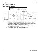
4. Capacity Range
4.1 Connection
Ratio
Type
Min.
connection
ratio
Max. connection ratio
Types of connected
indoor units
Type of connected air treatment
equipment
Low-temperature
hydrobox
4
When using
only
FXDQ-M,
FXSQ07-54TB,
FXMQ-PB,
FXAQ-P
When using at
least one
FXFQ07/09T,
FXZQ05TB,
FXSQ05TB
Other
indoor unit
models
FXMQ-MF
When only
FXMQ-MF is
connected
When
FXMQ-MF and
indoor units
are connected
When HXY-A and
indoor units are
connected
Single
outdoor
units
6-14 ton
50%
200%
1
180%
1
200%
1
100%
100%
2
130%
3
16-20 ton
180%
1
180%
1
Double outdoor
units
160%
1
160%
1
Notes:
1.
2.
3.
4.
If the operational capacity of indoor units is more than 130%, low airflow operation is enforced in all the
indoor units. This limitation can be deactivated through field setting. Refer to page 202 for detail.
When outdoor-air processing units (FXMQ-MF) and standard indoor units are connected, the total
connection capacity of the outdoor-air processing units (FXMQ-MF) must not exceed 30% of the capacity
index of the outdoor units. And the connection ratio must not exceed 100%.
When connecting the hydrobox, to prevent temporary water temperature drop on the secondary side of the
hydrobox at the time of defrosting or when the indoor unit starts/stops, and to prevent freezing, connect the
indoor unit with 50% or more capacity of the outdoor unit.
Mixed combination of FXMQ-MF and hydrobox in the system is not allowed.
Connection ratio =
Total capacity index of the indoor units
Capacity index of the outdoor units
Содержание VRV EMERION RXYQ-AATJA
Страница 1: ...Service Manual Heat Pump 60 Hz RXYQ AATJA 208 230 V RXYQ AAYDA 460 V SiUS342303E...
Страница 380: ...Check SiUS342303E 373 Part 6 Service Diagnosis Reference Reference CHECK 7 Refer to page 379 CHECK 8 Refer to page 380...
Страница 405: ...SiUS342303E Wiring Diagrams Part 7 Appendix 398 RXYQ72 96 120 144 168 192 216 240AAYDA C 2D140769B...
Страница 406: ...Wiring Diagrams SiUS342303E 399 Part 7 Appendix 1 2 Indoor Unit FXFQ07 09 12 15 18 24 30 36 48TVJU 3D086460B...
Страница 407: ...SiUS342303E Wiring Diagrams Part 7 Appendix 400 BYCQ125BGW1 Self Cleaning Decoration Panel for FXFQ TVJU 3D076375A...
Страница 410: ...Wiring Diagrams SiUS342303E 403 Part 7 Appendix FXEQ07 09 12 15 18 24PVJU 3D098557A...
Страница 411: ...SiUS342303E Wiring Diagrams Part 7 Appendix 404 FXDQ07 09 12 18 24MVJU C 3D050501C...
Страница 413: ...SiUS342303E Wiring Diagrams Part 7 Appendix 406 FXMQ07 09 12 15 18 24 30 36 48 54PBVJU 3D093209B...
Страница 416: ...Wiring Diagrams SiUS342303E 409 Part 7 Appendix FXHQ12 24 36MVJU 3D048116C...
Страница 417: ...SiUS342303E Wiring Diagrams Part 7 Appendix 410 FXAQ07 09 12 18 24PVJU 3D075354F...
Страница 423: ...SiUS342303E Wiring Diagrams Part 7 Appendix 416 1 3 2 Energy Recovery Ventilator VAM Series VAM300 470 600GVJU 3D073269D...
Страница 424: ...Wiring Diagrams SiUS342303E 417 Part 7 Appendix VAM1200GVJU 3D073270D...


