


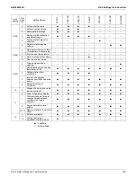


Field Settings for Indoor Unit
SiUS342303E
169
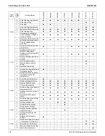
Part 5 Field Settings and Test Operation
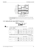
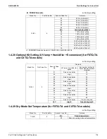
1.4.14 Dry Mode Set Temperature (for FXZQ-TB, FXUQ-PA, FXSQ-TB, and
FXMQ-TB models)
1.4.15 Optional Output Switching
Using this setting, "operation output signal" and "abnormal output signal" can be provided. Output
signal is output between terminals X1 and X2 of "adaptor for wiring", an optional accessory.
: Factory setting
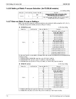
1.4.16 External ON/OFF Input
This input is used for "ON/OFF operation" and "Protection device input" from the outside. The input
is performed from the T1-T2 terminal of the operation terminal block in the electrical component
box.
: Factory setting
: Factory setting
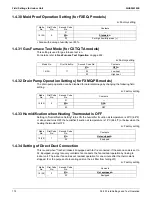
Mode No.
First Code No.
Second Code No.
Contents
11 (21)
12
01
Room temperature
02
Same as cooling mode set temperature
Mode
No.
First Code
No.
Second Code
No.
Contents
12 (22)
0
01
Indoor unit thermostat ON/OFF signal is provided.
02
—
03
Output linked with "Start/Stop" of remote controller is provided.
04
In case of "Error Display" appears on the remote controller, output is
provided.
05
—
06
—
07
Only for FXSQ-TB, FXMQ-PB, FXMQ-TB
Economizer (field supply) ON/OFF signal is provided.
Mode
No.
First Code
No.
Second
Code No.
Contents
12 (22)
1
01
ON: Forced stop (prohibition of using the remote controller)
OFF: Permission of using the remote controller
02
OFF
ON: Permission of operation
ON
OFF: Stop
03
ON: Operation
OFF: The system stops, then the applicable unit indicates
A0
. The other
indoor units indicate
U9
.
04
—
05
Only for FXMQ-PB
ON: Economizer (field supply) is connected.
OFF: Not connected
06
—
07
Only for FXSQ-TB, FXMQ-TB
ON: Economizer (field supply) is connected.
OFF: Not connected
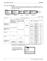
F2 T1 T2
Forced stop
Input A
Содержание VRV EMERION RXYQ-AATJA
Страница 1: ...Service Manual Heat Pump 60 Hz RXYQ AATJA 208 230 V RXYQ AAYDA 460 V SiUS342303E...
Страница 380: ...Check SiUS342303E 373 Part 6 Service Diagnosis Reference Reference CHECK 7 Refer to page 379 CHECK 8 Refer to page 380...
Страница 405: ...SiUS342303E Wiring Diagrams Part 7 Appendix 398 RXYQ72 96 120 144 168 192 216 240AAYDA C 2D140769B...
Страница 406: ...Wiring Diagrams SiUS342303E 399 Part 7 Appendix 1 2 Indoor Unit FXFQ07 09 12 15 18 24 30 36 48TVJU 3D086460B...
Страница 407: ...SiUS342303E Wiring Diagrams Part 7 Appendix 400 BYCQ125BGW1 Self Cleaning Decoration Panel for FXFQ TVJU 3D076375A...
Страница 410: ...Wiring Diagrams SiUS342303E 403 Part 7 Appendix FXEQ07 09 12 15 18 24PVJU 3D098557A...
Страница 411: ...SiUS342303E Wiring Diagrams Part 7 Appendix 404 FXDQ07 09 12 18 24MVJU C 3D050501C...
Страница 413: ...SiUS342303E Wiring Diagrams Part 7 Appendix 406 FXMQ07 09 12 15 18 24 30 36 48 54PBVJU 3D093209B...
Страница 416: ...Wiring Diagrams SiUS342303E 409 Part 7 Appendix FXHQ12 24 36MVJU 3D048116C...
Страница 417: ...SiUS342303E Wiring Diagrams Part 7 Appendix 410 FXAQ07 09 12 18 24PVJU 3D075354F...
Страница 423: ...SiUS342303E Wiring Diagrams Part 7 Appendix 416 1 3 2 Energy Recovery Ventilator VAM Series VAM300 470 600GVJU 3D073269D...
Страница 424: ...Wiring Diagrams SiUS342303E 417 Part 7 Appendix VAM1200GVJU 3D073270D...