21
|
Configuration
Installer and user reference guide
143
RYMA5+RXYA8~20A7Y1B
VRV 5 heat pump
4P749918-1 – 2023.12
b
Push buttons
c
DIP switches
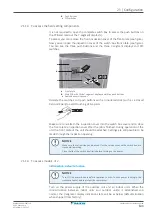
21.1.3 To access the field setting components
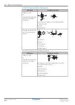
It is not required to open the complete switch box to access the push buttons on
the PCB and read out the 7‑segment display(s).
To access you can remove the front inspection cover of the front plate (see figure).
Now you can open the inspection cover of the switch box front plate (see figure).
You can see the three push buttons and the three 7‑segment displays and DIP
switches.
2×
a
b
c
a
Front plate
b
Main PCB with three 7‑segment displays and three push buttons
c
Switch box service cover
Operate the switches and push buttons with an insulated stick (such as a closed
ball-point pen) to avoid touching of live parts.
Make sure to re-attach the inspection cover into the switch box cover and to close
the front plate's inspection cover after the job is finished. During operation of the
unit the front plate of the unit should be attached. Settings are still possible to be
made through the inspection opening.
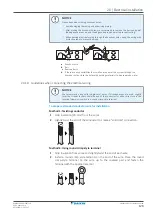
NOTICE
Make sure that all outside panels, except for the service cover on the switch box, are
closed while working.
Close the lid of the switch box firmly before turning on the power.
21.1.4 To access mode 1 or 2
Initialisation: default situation
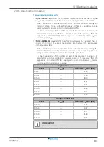
NOTICE
Turn ON the power 6 hours before operation in order to have power running to the
crankcase heater and to protect the compressor.
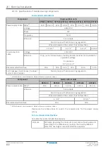
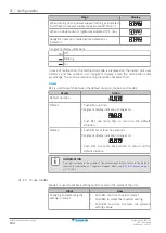
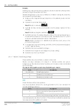
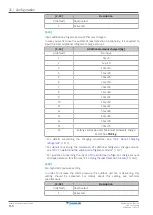
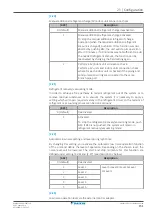
Turn on the power supply of the outdoor unit and all indoor units. When the
communication between indoor units and outdoor unit(s) is established and
normal, the 7‑segment display indication state will be as below (default situation
when shipped from factory).
Содержание VRV 5 RXYA8A7Y1B
Страница 197: ......
Страница 198: ......
Страница 199: ......
Страница 200: ...4P749918 1 2023 12 Copyright 2023 Daikin Verantwortung f r Energie und Umwelt...

