Daikin VKM100GAMV1 Скачать руководство пользователя страница 27

Operation

Si71-812

18

Operation

1.4

Restrictions to Control System

1.4.1 Do not Give VKM-GA(M) Model a Function to Select Cooling/Heating.

(This is because the operation mode switches automatically 
depending on the outdoor conditions regardless of the indoor 
temperature when set to "Automatic".)

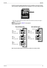
1.4.2 Caution when Connecting with a VRV System, Heat Recovery Type

When bringing the RA (exhaust gas intake) of this unit directly in from the ceiling, connect to a BS unit 
identical to the VRV indoor unit (master unit), and use group-linked operation.

Caution

If above setting is not made, the detection of correct temperature is not available and automatic judgment 
on proper cooling or heating can not be made when the temperature in the ceiling gets higher than indoor 
temperature.
Poor heating or shortage of the amount of humidification may result.

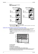
If the indoor unit and this unit are installed with different BS system inevitably, always take following 
remedies (1) and (2).
(1) RA (Exhaust and suction) of this unit is not taken directly from inside of the ceiling, connect the suction 

duct and suction grille to the fitting port of RA duct to suck the indoor air.

(2) Do not make the selection of heating or cooling in automatic mode and it shall be made by manual 

selection from remote controller or centralized controller.

Give a function to select cooling/heating to either one of these.

EA

OA

RA

SA

• 

The system must be operated interlocking 

with the air conditioner.

BS Unit

BS Unit

Give a function to select cooling/heating to either one of these.

Outdoor unit for heat recovery

EA

OA

RA

SA

Give a function to select cooling/heating to either one of these.

BS Unit

BS Unit

Outdoor unit for heat recovery

Suction
grille

Содержание VKM100GAMV1

Страница 1: ...Si71 812 Heat Reclaim Ventilation with DX coil Applied Models VKM 50GAV1 VKM 80GAV1 VKM 100GAV1 VKM 50GAMV1 VKM 80GAMV1 VKM100GAMV1 ...

Страница 2: ...cation 6 1 1 With DX coil Humidifier 6 1 2 With DX coil 8 1 3 Humidifier 10 Part 3 Operation 11 1 Operation 12 1 1 Explanation for Systems 12 1 2 Features of VKM GA M 15 1 3 Central Control System 17 1 4 Restrictions to Control System 18 1 5 Operation 20 Part 4 Maintenance 35 1 Maintenance 36 1 1 Maintenance for the Air Filter 36 1 2 Maintenance for the Heat Exchange Element 38 2 Inspection and Ma...

Страница 3: ...rmistor R4T for Heat Exchanger 64 2 10 C5 Indoor Unit Malfunction of Thermistor R5T for Gas Pipes 65 2 11 C9 Indoor Unit Malfunction of Thermistor R3T for Suction Air 66 2 12 U3 Check Operation not Executed 67 2 13 Dedicated LCD Remote Controller 68 2 14 Data Transmission Error between LCD Remote Controller and Main Unit 69 2 15 U5 Malfunction of Transmission between Remote Controller and Indoor U...

Страница 4: ...Si71 812 Table of Contents iii Part 8 Appendix 89 1 Appendix 90 1 1 Wiring Diagram 90 1 2 List of Electrical and Functional Parts 92 2 Piping Diagram 93 Index i Drawings Flow Charts iii ...

Страница 5: ... disassembling the equipment for a repair Working on the equipment that is connected to a power supply can cause an electrical shook If it is necessary to supply power to the equipment to conduct the repair or inspecting the circuits do not touch any electrically charged sections of the equipment If the refrigerant gas discharges during the repair work do not touch the discharging refrigerant gas ...

Страница 6: ...e applicable model and appropriate tools to conduct repair work Never attempt to modify the equipment The use of inappropriate parts or tools can cause an electrical shock excessive heat generation or fire When relocating the equipment make sure that the new installation site has sufficient strength to withstand the weight of the equipment If the installation site does not have sufficient strength...

Страница 7: ...ce valve to prevent the refrigerant gas from leaking into the room The refrigerant gas itself is harmless but it can generate toxic gases when it contacts flames such as fan and other heaters stoves and ranges When replacing the coin battery in the remote controller be sure to disposed of the old battery to prevent children from swallowing it If a child swallows the coin battery see a doctor immed...

Страница 8: ...l shock Be sure to measure the insulation resistance after the repair and make sure that the resistance is 1 Mohm or higher Faulty insulation can cause an electrical shock Be sure to check the drainage of the indoor unit after the repair Faulty drainage can cause the water to enter the room and wet the furniture and floor Icon Type of Information Description Note Note A note provides information t...

Страница 9: ...Introduction Si71 812 viii ...

Страница 10: ...Si71 812 General Constructions 1 Part 1 General Constructions 1 General Information 2 1 1 Features 2 ...

Страница 11: ... Features 1 1 1 External Appearance VKM50GAMV1 VKM50GAV1 VKM80GAMV1 VKM100GAMV1 VKM80GAV1 VKM100GAV1 1 1 2 Model Series These units are applied only for CE regulation Type 500 800 1000 DX Coil and Humidifier VKM50GAMV1 VKM80GAMV1 VKM100GAMV1 DX Coil VKM50GAV1 VKM80GAV1 VKM100GAV1 ...

Страница 12: ...1 1 4 Structures V K M 50 GA M V1 Ventilation Outdoor Air Treatment Type Mounted Type Major Design Category Moisture M With Humidifier Elements nothing without Humidifier Elements Power Supply V1 1 Phase 220 240V 50Hz Nominal Air Flow Rate 50 500m3 h 80 750m3 h 100 950m3 h ...

Страница 13: ...appendices Type indoor unit of VRV Installation box for adaptor PCB Unified ON OFF controller Schedule timer For ON signal output For heater control kit BRC1A62 1 BRC1D527 EU only Note 8 DCS302CA61 DCS301BA61 DST301BA61 KRP2A61 KRP50 2 BRP4A50 Member Applicable model Controlling device PC Board Adaptor Centralized controlling device Note 1 2 3 4 Installation box is necessary for each adaptor marke...

Страница 14: ...Si71 812 Product Specification 5 Part 2 Product Specification 1 Product Specification 6 1 1 With DX coil Humidifier 6 1 2 With DX coil 8 1 3 Humidifier 10 ...

Страница 15: ...te Insulating Material Self Extinguishable Urethane Foam Heat Exchanging System Air to Air Cross Flow Total Heat Sensible Latent Heat Exchange Heat Exchanger Element Specially Processed Nonflammable Paper Air Filter Multidirectional Fibrous Fleeces Coil Cross Fin Coil Rows Stages Fin Pitch mm 2 12 2 2 Face Area m2 0 078 0 118 0 165 Cooling Capacity Note 2 kW 4 71 1 91 7 46 2 96 9 12 3 52 Heating C...

Страница 16: ...door RA return air from room 11 The specifications designs and information here are subject to change without notice 12 Temperature Exchange Efficiency is a mean value in cooling and heating 13 Efficiency is measured under the following conditions Ratio of rated external static pressure has been kept as follows Outdoor side to indoor side 7 to 1 14 Feed clean water If the supply water is hard wate...

Страница 17: ...ized Steel Plate Insulating Material Self Extinguishable Urethane Foam Heat Exchanging System Air to Air Cross Flow Total Heat Sensible Latent Heat Exchange Heat Exchanger Element Specially Processed Nonflammable Paper Air Filter Multidirectional Fibrous Fleeces Coil Cross Fin Coil Rows Stages Fin Pitch mm 2 12 2 2 Face Area m2 0 078 0 118 0 165 Cooling Capacity Note 2 kW 4 71 1 91 7 46 2 96 9 12 ...

Страница 18: ...r High mode 7 Normal Amp input efficiency depend on the above air flow rate value 8 OA fresh air from outdoor RA return air from room 9 The specifications designs and information here are subject to change without notice 10 Temperature Exchange Efficiency is a mean value in cooling and heating 11 Efficiency is measured under the following conditions Ratio of rated external static pressure has been...

Страница 19: ...5 50 C and its pressure at 20 490 kPa 0 2 5 0 kg cm2 If the water pressure is above 490 kPa 5 0 kg cm2 add pressure reducing valve in between the kit and the supply water shut off valve 3 The supply water line cannot be directly connected with a utility water tap To unavoidably take water from such line employ a CISTERN gotten configuration authorization 4 Be sure to provide thermal insulation aro...

Страница 20: ...Si71 812 Operation 11 Part 3 Operation 1 Operation 12 1 1 Explanation for Systems 12 1 2 Features of VKM GA M 15 1 3 Central Control System 17 1 4 Restrictions to Control System 18 1 5 Operation 20 ...

Страница 21: ...on of HRV VKM s and air conditioners by using the air conditioner remote controller The HRV VKM unit can also be operated independently using the remote controller for the indoor unit even if the indoor unit is not in operation VRV remote controller Independent Operation System Independent Operation Simultaneous Operation of Multiple Units 0 1 2 3 VRV Up to 16 Up to 14 Up to 12 Up to 10 4 5 6 7 8 ...

Страница 22: ...lized transmission line in one system which enables control of up to 128 groups 16 groups x 8 128 groups Schedule Timer One schedule timer can control the weekly schedule of up to 128 units Unified ON OFF controller or schedule timer VRV remote controller When necessary centralized controller Centralized controller VRV remote controller When necessary unified ON OFF controller or schedule timer In...

Страница 23: ...der to interlock between the VKM and the indoor unit the group control of remote controllers should be provided Fig 1 When interlocking between the base indoor unit and the VKM Connect multiple indoor units and VKM to a single BS unit Fig 2 When connecting a single indoor unit or a single VKM to a single BS unit If this is the case use the VKM in fixed cooling or heating mode 3 Measures against in...

Страница 24: ...s been built in in addition to a PC board for ventilation These two PC boards are connected via remote controller line P1 P2 to perform an interlocked control Its control system provides the same condition when 1 ventilation and 1 VRV air conditioner have been remotely controlled No air conditioning temperature controlling function has been equipped Therefore it is necessary to prepare separately ...

Страница 25: ...group Because 2 pieces of controlling PC board have been built in a VKM GAM model count the remote controller group as 1 set 2 units The maximum number of units connectable to a remote controller group is 16 External contact point If you want to start stop through an external contact point use external input terminals T1 and T2 If you start stop using T1 and T2 terminals the entire remote controll...

Страница 26: ...t be kept as the factory setting 17 08 01 Structure without a remote controller cannot be accepted because the remote controller group is controlled within a VKM GA M model i Touch controller central remote controller Connection to central line is prohibited Remote controller for air conditioner Ventilation PC board Corresponding VRV indoor unit s PC board JC J2 T1 T2 Note 1 Centralized units F1 F...

Страница 27: ...n indoor temperature Poor heating or shortage of the amount of humidification may result If the indoor unit and this unit are installed with different BS system inevitably always take following remedies 1 and 2 1 RA Exhaust and suction of this unit is not taken directly from inside of the ceiling connect the suction duct and suction grille to the fitting port of RA duct to suck the indoor air 2 Do...

Страница 28: ...ings from the remote controller Mode No 17 27 First code No 5 Second code No 6 Refer to 15 10 1 concerning setting method b Do not connect to the outlet side of the indoor unit Depending on the fan strength and static pressure the unit might back up c When it is connected to the suction side of indoor unit as a direct duct connection system etc since there is a possibility that the body thermo of ...

Страница 29: ...sponds to your system type and mark If your installation has a customized control system ask your dealer for the operation that corresponds to your system Name of Parts Sometimes when first using the unit the smell of the heat exchanging element may be noticeable but it is not harmful The smell will gradually go away as the unit is used Important It exchanges the heat temperature and humidity from...

Страница 30: ...ns 1 On off button Press the button and the system will start Press the button again and the system will stop 2 Operation lamp red The lamp lights up during operation or blinks if a malfunction occurs 3 Display changeover under control May be displayed when combined with a VRV system air conditioner It is impossible to changeover heat cool with the remote controller when this icon is displayed 4 D...

Страница 31: ...imer Refer to page 31 15 Timer on off button Refer to the chapter Operation procedure Programming start and stop of the system with timer Refer to page 31 16 Inspection test operation button Pressed during inspection or test run Do not use under usual use service person installer only 17 Programming time button Use this button for programming start and or stop time 18 Temperature setting button Us...

Страница 32: ...chedule timer 38 ELEMENT CLEANING TIME ICON This icon indicates the element must be cleaned HRV only 39 PROGRAMMING BUTTON This button is a multi purpose button Depending on the previous manipulations of the user the programming button can have various functions 40 SCHEDULE TIMER BUTTON This button enables or disables the schedule timer 41 OPERATION CHANGE MIN MAX BUTTON This button is a multi pur...

Страница 33: ...can also select the ventilation amount and the ventilation mode During intermediate periods when only the HRV unit is used without the air conditioner select ventilation with the operation selection button Refer to About Direct Duct Connection System Sample system Independent system Operation The HRV unit can be started and stopped using the remote controller You can also select the ventilation am...

Страница 34: ...r BRC1D527 and as equivalent Display changes as below Note Current Ventilation mode can be visible and selected on the remote controller Operation mode display Ventilation is displayed Operation mode selector button Remote controller for indoor unit Operation mode VRV Cooling mode HRV Heat exchange mode VRV Fan mode HRV Heat exchange mode VRV Stopping HRV Heat exchange mode When air conditioner an...

Страница 35: ...tory settings so request your dealer to turn it on if you intend to use it Operation image a Outside temperature b Indoor temperature c Set temperature d Operating state of Air conditioner e Operating state of Total heat exchanger EXPLANATION OF NIGHTTIME FREE COOLING OPERATION IMAGE The unit compares the indoor and outdoor temperatures after the air conditioning operation stops for the night If t...

Страница 36: ...te controllers on which it is displayed See page 29 if is displayed Press ventilation mode selector button if you wish to change the mode The display rotates through the following selections every time the button is pressed Note Above is available only if the remote controller BRC1D527 is connected with this unit It is unnecessary to change ventilation mode because the mode is already set to autom...

Страница 37: ...ing alone Total heat exchange mode Outdoor air passes through the heat exchange element and heat exchanged air is sent into the room Bypass mode In this mode outdoor air does not through the heat exchange element but rather sent into the room as is EXPLANATION OF HEATING OPERATION Defrost operation In heating operation freezing of the outdoor unit coil increases Heating capability decreases and th...

Страница 38: ...other indoor units set the master remote controller on the other indoor units Press the operation mode selector button of the controller that you wish to designate as the master remote controller Then designation is completed This remote controller is designated as the master remote controller and the display showing changeover under control vanishes The displays of other remote controller show ch...

Страница 39: ...oling heating mode will make slave remote controllers with the display to follow to the mode of the master remote controller Selection of fan mode is possible however Setting the master remote controller without the display to fan mode will make slave remote controllers with the display any setting other than fan mode impossible ...

Страница 40: ...ces or goes backward by 1 hour The timer can be programmed for a maximum of 72 hours Each time when is pushed the time advances one hour Each time when is pushed the time goes back one hour Press the timer on off button The timer setting procedure ends The display or changes from flashing light to constant light After the timer is programmed the display shows the remaining time For cancelling the ...

Страница 41: ...n The icon appears will blink and one of the icons one of the icons might be displayed but all other fields remain blank indicating that no actions are programmed for Monday Enter the program mode by holding down the button for 5 seconds the icon will now blink too Press the button to activate the first programmed action A blinking 1 is displayed indicating that the first programmed action for Mon...

Страница 42: ...ation to form on the main unit or on discharge grill or around air supply opening Keep the indoor unit and the remote controller at least 1 m away from televisions radios stereos and other similar equipments This may cause distorted picture or noise Turn off the main power supply switch when it is not used for long periods of time When the main power switch is turned on some watts of electricity i...

Страница 43: ...Operation Si71 812 34 Operation ...

Страница 44: ...Maintenance 1 Maintenance 36 1 1 Maintenance for the Air Filter 36 1 2 Maintenance for the Heat Exchange Element 38 2 Inspection and Maintenance of the Humidifier 39 2 1 For VKM GAMV1 Series 39 2 2 Replacing the Humidifier Element 43 ...

Страница 45: ... FOR GENERAL OFFICE USE CLEAN THE ELEMENT MORE FREQUENTLY IF NECESSARY 1 Go into ceiling through the inspection hole remove the hanging metals of maintenance cover and take it off VKM50 100GA M 2 Detach the air filter Take out from the heat exchange elements VKM50 100GA M 3 Clean the air filter Use vacuum cleaner or wash the air filter with water When the air filter is very dirty use soft brush an...

Страница 46: ...ade When dried completely install the air filter back in place Note Be sure to install the air filter after servicing Missing air filter causes clogged heat exchange element The air filter is an optional item and the replacement is available 5 Install the maintenance cover See P85 if you want to change the time setting for when the filter sign goes on Note Do not remove the air filter except when ...

Страница 47: ...f the suction nozzle Lightly contact the brush on the surface of the heat exchanging element when cleaning Do not crush the heat exchange element while cleaning Caution Do not clean touching strongly with a vacuum cleaner This may crush the mesh of the heat exchange elements Never wash the heat exchange element with water Have your dealer professionally clean the filter if it is very dirty 2 Insta...

Страница 48: ...lose the water supply shut off valve and open the drain valve of the water supply piping Fig 1 Before all working please cure a piping part and below product Fig 1 2 1 1 Inspection of Strainer Check for clogging Check O ring for cracks 1 Please loosen the cap of the strainer of a water supply entrance part 2 Please take out and clean the element inside a strainer Fig 2 3 Please attach an element a...

Страница 49: ...e Humidifier elements Fig 4 10 Install the hold plate Fig 4 11 Install the cover of the feed water tank Fig 4 12 Confirm that the link of the supporting stay has been hooked securely on the rail and insert it Fig 8 Refit the supporting stay handling part without contacting the lid of feed water tank Fig 8 Insert the supporting stay securely and fix it with the screws Fig 8 13 Install the maintenan...

Страница 50: ...Si71 812 Inspection and Maintenance of the Humidifier Maintenance 41 Fig 5 Fig 6 Fig 7 Fig 8 screw Hook surely the supporting stay on the rail rail supporting stay ...

Страница 51: ...oat switch operation 1 Check that the water supply piping is connected securely 2 Open the water supply shut off valve No water will be supplied at this time 3 Run the HRV unit in heating mode See the operating manual included with the indoor unit for details on how to run the unit in heating mode The water supply will start and the humidifier will begin operation 4 After starting heating humidify...

Страница 52: ...erating conditions 24 hour a day air conditioning etc may shorten its productive life Contact your dealer if you have any questions Life of humidifying element is about 3 years 4 000 hours under the supply water conditions of hardness 150mg l Life of humidifying element is about 1 year 1 500 hours under the supply water conditions of hardness 400mg l Annual operating hours 10 hours day 26 days mon...

Страница 53: ...Inspection and Maintenance of the Humidifier Si71 812 44 Maintenance ...

Страница 54: ...Si71 812 Control Functions 45 Part 5 Control Functions 1 Control Functions 46 1 1 Explanation of individual Functions 46 1 2 Layout of Switches on Printed Circuit Board 52 ...

Страница 55: ...tion Air conditioning operation carries out to April to October and air conditioning load is calculated only with sensible heat load Note Nighttime free cooling operation setting can be set using field setting mode remote controller In detail refer to page 85 Stop Night Morning Heat Release Heat Release Cold Air In case of interlocking operation with an air conditioner Heat Reserve Heat Reserve He...

Страница 56: ...ime Setup time Indoor temp Preset temp 2 C Indoor temp Outdoor temp Yes Yes No No No No No Yes Yes Yes No No No Fan operation Temperature monitor 5Min Fan operation ON H or U H tap Lapsed time setup 2hr 4hr 6hr 8hr No Air conditioner Operation RUN Temp monitor operation time Lapsed time 60hr Indoor temp Outdoor temp Indoor temp Preset temp Fan operation Lapsed time Lapsed time 60Min Standard mode ...

Страница 57: ...eration the fans of the unit continues driving factory setting The purpose of this is to maintain the amount of ventilation and humidifying Though the fan can be stopped by the setting of the remote controller In detail refer to page 85 Operation By pass mode selection Air conditioner ON OFF Operation Fan motor Heat reclaim ventilation unit Ventilation fan motor Damper motor ventilation mode Total...

Страница 58: ...ing changes should be made in the following way Mode No 18 group tie up or 28 Setting switch No 7 Setting position No 1 No 4 Refer to page 85 Exhaust fan Air supply fan DX coil cooling Damper Heat exchanger element heat recovery EA OA RA SA Humidifying DX coil heating Heat exchanger element heat recovery EA OA RA SA EA OA RA SA Cooling In between bypass ventilation Heating Automatic changeover Aut...

Страница 59: ...trol of 2 or more groups zone link Heat reclaim ventilation unit can be operated when one or more air conditioners are operating Allows independent operation of heat reclaim ventilation unit from VRV system remote controller during interim periods direct duct connection is not allowed in this system ON OFF operation is not possible from LCD remote controller of heat reclaim ventilation unit Note W...

Страница 60: ...the X15A on the print board and the other end to the harness leading to the damper via a connector such as a closed connector With regard to closed connector select one that suits wire diameter Note Location of X15A Refer to next page Essential Setting Changes The X15A output is at the default setting and is not in operation so the output setting should be changed at the LCD of the remote controll...

Страница 61: ...Control Functions Si71 812 52 Control Functions 1 2 Layout of Switches on Printed Circuit Board 1 2 1 Printed Circuit Board VKM GAMV1 A1P A3P VKM GAV1 2P130159G 2P124140C ...

Страница 62: ...0 C5 Indoor Unit Malfunction of Thermistor R5T for Gas Pipes 65 2 11 C9 Indoor Unit Malfunction of Thermistor R3T for Suction Air 66 2 12 U3 Check Operation not Executed 67 2 13 Dedicated LCD Remote Controller 68 2 14 Data Transmission Error between LCD Remote Controller and Main Unit 69 2 15 U5 Malfunction of Transmission between Remote Controller and Indoor Unit 70 2 16 U8 Malfunction of Transmi...

Страница 63: ...ion button for more than 4 seconds Press Inspection Test Operation button once Press Inspection Test Operation button once Or after 30 minutes After 10 seconds Press Inspection Test Operation button once Press Inspection Test Operation button once Indoor unit settings can be made Filter sign time Air flow direction Others Following codes can be checked Malfunction codes Indoor model code Outdoor m...

Страница 64: ... malfunction the remote controller s operation LED blinks and malfunction code is displayed Even if stop operation is carried out malfunction contents are displayed when the inspection mode is entered The malfunction code enables you to tell what kind of malfunction caused operation to stop See page 56 for malfunction code and malfunction contents ...

Страница 65: ...per related malfunction thermistor malfunction 61 Blinking Blinking Blinking A1 Printed circuit board fault 62 On Off Blinking A1 Printed circuit board fault 62 Blinking Blinking Blinking A9 Electric expansion valve drive error 63 Blinking Blinking Blinking C4 Liquid piping thermistor R4T error faulty connection disconnection short circuit fault 64 Blinking Blinking Blinking C5 Gas piping thermist...

Страница 66: ...A 9 E Outdoor model code Model RSXYP RXYP RSEYP RSXYP L RXYQ M RXYQ MA RXYQ P RXQ P REYQ P Unit Malfunction code Inspection Normal display No display 0 L 0 Malfunction code blinks when a malfunction occurs Unit Malfunction code Inspection Inspection mode Push the button Inspection test operation Push the button Inspection test operation Push the button Inspection test operation Push the button Ins...

Страница 67: ...sistance conversion table If measured value deviates significantly from above values thermistor is faulty Use tester to check resistance Remove Indoor air thermistor R1T from X12A 3P on control PC board A1P and measure resistance Is thermistor normal Note 1 YES NO Replace indoor air thermistor If there is no faulty contact replace control PC board HF003 Caution Be sure to turn off power switch bef...

Страница 68: ...sistance conversion table If measured value deviates significantly from above values thermistor is faulty Use tester to check resistance Remove outdoor air thermistor R2T from X13A 2P on control PC board A1P and measure resistance Is thermistor normal Note 1 YES NO Replace outdoor air thermistor If there is no faulty contact replace control PC board HF004 Caution Be sure to turn off power switch b...

Страница 69: ...oard A1P assembly Troubleshooting Note Note 1 Place tester probes on connectors of limit switch Move switch by hand and check continuity If tester indicates 0Ω when limit switch turns on and infinity when it turns off limit switch is normal Place tester probes on connectors of damper motor and check resistance If tester indicates approx 17 kΩ in 200 V model damper motor is normal Check connectors ...

Страница 70: ...door air thermistor Frosting Broken wire in cable Faulty contact in connector including relay connector Faulty control PC board A1P assembly Troubleshooting Check error record on malfunction history display in service mode Is 64 recorded YES YES YES Take corrective measures specified for damper system error alarm Remove the cause of problem and reset display Take corrective measures specified for ...

Страница 71: ...rom the E PROM E PROM Type of nonvolatile memory Maintains memory contents even when the power supply is turned off Supposed Causes Defect of indoor unit PC board A2P Troubleshooting Turn power supply OFF then power ON again Does the system return to normal YES External factor other than malfunction for example noise etc Replace the indoor unit PC board A2P V2777 NO Caution Be sure to turn off pow...

Страница 72: ...e Defect of indoor unit PC board A2P Defect of connecting cable Troubleshooting V2781 Caution Be sure to turn off power switch before connect or disconnect connector or parts damage may be occurred After connecting turn the power supply off and then back on Replace the moving part of the electronic expansion valve YES YES NO NO Replace the connecting cable If you turn the power supply off and turn...

Страница 73: ... the unit is running Supposed Causes Defect of thermistor R4T for liquid pipe Defect of indoor unit PC board A2P Troubleshooting 2 Refer to thermistor resistance temperature characteristics table on P79 V2784 Caution Be sure to turn off power switch before connect or disconnect connector or parts damage may be occurred Replace the indoor unit PC board Connect the thermistor and turn on again NO NO...

Страница 74: ...running Supposed Causes Defect of indoor unit thermistor R5T for gas pipe Defect of indoor unit PC board A2P Troubleshooting 2 Refer to thermistor resistance temperature characteristics table on P79 V2785 Caution Be sure to turn off power switch before connect or disconnect connector or parts damage may be occurred Replace the indoor unit PC board Connect the thermistor and turn on again NO NO Rep...

Страница 75: ...ile the unit is running Supposed Causes Defect of indoor unit thermistor R3T for air inlet Defect of indoor unit PC board A2P Troubleshooting 2 Refer to thermistor resistance temperature characteristics table on P79 Caution Be sure to turn off power switch before connect or disconnect connector or parts damage may be occurred Replace the indoor unit PC board Connect the thermistor and turn on agai...

Страница 76: ... when the unit starts operation without check operation Supposed Causes Check operation is not executed Troubleshooting V3052 Has the check operation performed on Outdoor unit PC board Press the BS4 on PC board on the master outdoor unit for 5 seconds or more to execute check operation Replace the main PC board on the outdoor unit NO YES Caution Be sure to turn off power switch before connect or d...

Страница 77: ... see if master slave remote controller is used Check microcomputer operation monitor on main unit PC board Is it flashing YES YES Change master slave selection switch to set proper master slave relation One should be set to Master and the other set to Slave Replace remote controller Replace main unit PC board Is master slave remote controller used HF007 NO NO Caution Be sure to turn off power swit...

Страница 78: ...ote controller cable disconnected voltage between P1 and P2 on terminal board should be approx 16 VDC If measured value is not approx 16 VDC PC board assembly is faulty Connect remote controller cable and disconnect remote controller Voltage at the end of remote controller cable should be approx 16 VDC If measured value is not 16 VDC remote controller cable is faulty Connect remote controller cabl...

Страница 79: ...of remote controller PC board Malfunction of transmission caused by noise Troubleshooting Caution Be sure to turn off power switch before connect or disconnect connector or parts damage may be occurred V2823 NO YES YES NO Replace indoor unit PC board Set one remote controller to SLAVE turn the power supply off once and then back on There is possibility of malfunction caused by noise Check the surr...

Страница 80: ... period Supposed Causes Malfunction of transmission between main and sub remote controller Connection between sub remote controllers Defect of remote controller PC board Troubleshooting Caution Be sure to turn off power switch before connect or disconnect connector or parts damage may be occurred V2825 SS1 of both remote controllers is setto SUB Set SS1 to MAIN the power supply off once and then b...

Страница 81: ...type of outdoor unit Caution Be sure to turn off power switch before connect or disconnect connector or parts damage may be occurred V2827 The total of indoor units displaying UA and indoor units connected to the same refrigerant system is within connectable number of unit Normal NO NO There are too many indoor units within the same refrigerant system Push and hold the RESET button on the outdoor ...

Страница 82: ...uses Address duplication of centralized remote controller Defect of indoor unit PC board Troubleshooting Caution Be sure to turn off power switch before connect or disconnect connector or parts damage may be occurred V2828 Replace indoor unit PC board Address duplication of central remote controller The setting must be changed so that the central remote control address is not duplicated YES NO Opt...

Страница 83: ...Microcomputer checks if transmission between indoor unit and centralized remote controller is normal Malfunction Decision Conditions When transmission is not carried out normally for a certain amount of time Supposed Causes Malfunction of transmission between optional controllers for centralized control and indoor unit Connector for setting master controller is disconnected Failure of PC board for...

Страница 84: ... the master controller s connector for setting master controller disconnected Set the group No correctly Replace indoor unit PC board Fix the wiring correctly Fix the wiring correctly Connect the connector correctly Replace the central PC board Reset power supply simultaneously for all optional controllers for centralized control YES YES NO YES YES YES YES Turn indoor unit s power supply YES NO NO...

Страница 85: ...n Be sure to turn off power switch before connect or disconnect connector or parts damage may be occurred Is the power supply turned on for indoor units displaying malfunction Is transmission wiring disconnected or wired incorrectly Is the transmission wiring with the master controller disconnected or wired incorrectly Is the master controller s connector for setting master controller disconnected...

Страница 86: ...ble causes replace PC board assembly Is monitor indicator Off YES YES Monitor indicator remains On With remote controller disconnected check microcomputer operation monitor Turn off power then restart Noise may be causing erroneous operation If power reset does not solve the problem replace main unit PC board There may be a malfunction in main unit PC board fuse main unit PC board or power transfo...

Страница 87: ... Note Refer to the thermistor temperature resistance conversion table when measuring resistance NO YES Is resistance as shown below Thermistor is normal Remove thermistors from main unit PC board A1P X12A X13A and PC board A2P X13A X14A X15A check resistance using tester If measured value deviates significantly from values in the table thermistor is faulty HF015 Caution Be sure to turn off power s...

Страница 88: ...54 4 81 08 78 97 46 8 37 8 21 3 76 93 74 94 47 8 05 7 90 2 73 01 71 14 48 7 75 7 60 1 69 32 67 56 49 7 46 7 31 0 65 84 64 17 50 7 18 7 04 1 62 54 60 96 51 6 91 6 78 2 59 43 57 94 52 6 65 6 53 3 56 49 55 08 53 6 41 6 53 4 53 71 52 38 54 6 65 6 53 5 51 09 49 83 55 6 41 6 53 6 48 61 47 42 56 6 18 6 06 7 46 26 45 14 57 5 95 5 84 8 44 05 42 98 58 5 74 5 43 9 41 95 40 94 59 5 14 5 05 10 39 96 39 01 60 4...

Страница 89: ...se 100 MΩ or higher Insulation resistance between primary side and secondary side of transformer 100 MΩ or higher Check resistance of primary side of transformer Does measured resistance deviate significantly from values shown below YES NO Check resistance of secondary side of transformer Does measured resistance deviate significantly from values shown below YES NO Apply rated voltage to primary s...

Страница 90: ...red value 0 Ω when limit switch turns on and infinity when it turns off Damper motor is normal Place tester probes at connectors of limit switch and check continuity while moving switch by hand Limit switch is faulty Damper motor is faulty HF017 NO Is measured value of EJ type approx 17 kΩ Place tester probes on connectors of damper motor and check resistance Caution Be sure to turn off power swit...

Страница 91: ...Troubleshooting Si71 812 82 Troubleshooting ...

Страница 92: ...Si71 812 Field Setting 83 Part 7 Field Setting 1 Field Setting 84 1 1 Field Setting and Test Run 84 ...

Страница 93: ...llowing describes the operating procedure and settings 1 Press the INSPECTION TRIAL button for more than four seconds with the unit in the normal mode to enter the local setting mode 2 Use the TEMPERATURE ADJUSTMENT button to select the desired Mode No The code display will blink 3 To make settings for individual units under group control when mode No 27 28 or 29 is selected press the TIMER SETTIN...

Страница 94: ...r 8 hours later Fan speed initial setting 4 Normal Ultra high Direct duct connection with VRV setting 5 Notdirect duct Air flow setting Withdirect duct fan off Notdirect duct Air flow setting Withdirect duct fan off Setting for cold areas Fan operation selection for heater thermostat OFF NOTE 6 5 Air flow setting Air flow setting Fan L Fan L Ventilation air flow setting when Nighttime free cooling...

Страница 95: ...grill s location should be examined when the cold draft from air discharge grill is feared z Though the fan can be stopped by the setting of remote controller Do not stop the fan in the place where no ventilation by stopping the fan may cause the influence of diffusion of air which it is dirty and moisture into another room or the inflow from outside the room outflow such as viruses from the sickr...

Страница 96: ...y that the wiring was done incorrectly or that the power is not on so check again Remote control display Content is display z There is a short circuit at the FORCED OFF terminals T1 T2 is display z The test run has not be performed is display is display z The power on the outdoor unit is off z The outdoor unit has not been wired for power supply z Incorrect wiring for the transmission wiring and t...

Страница 97: ...n operation 4 After starting heating humidifying the sound of the water supply solenoid valve will be heard every 3 or 4 minutes a clicking sound so listening for that clicking sound let the unit run for 30 minutes to make sure that humidifying operation is normal CAUTION If carpentry work is not completed when a test run is finished tell the customer not to run the humidifier for the protection o...

Страница 98: ...Si71 812 Appendix 89 Part 8 Appendix 1 Appendix 90 1 1 Wiring Diagram 90 1 2 List of Electrical and Functional Parts 92 2 Piping Diagram 93 ...

Страница 99: ...Appendix Si71 812 90 Appendix 1 Appendix 1 1 Wiring Diagram VKM50GAMV1 VKM80GAMV1 VKM100GAMV1 ...

Страница 100: ...Si71 812 Appendix Appendix 91 VKM50GAV1 VKM80GAV1 VKM100GAV1 ...

Страница 101: ...per Motor M1D MG8 3P145772 2 AC220 240V Thermistors Thermistor Indoor Air R1T ST8601 15C φ4 L1000 20kΩ 25 C Thermistor Outdoor Air R2T 3SH40049 3 φ4 L2500 20kΩ 25 C Thermistor Inlet Air Into Coil R3T ST8601 6C φ4 L1000 20kΩ 25 C Thermistor Liquid Pipe of Coil R4T ST8602A 5 φ6 L1000 20kΩ 25 C Thermistor Gas Pipe of Coil R5T ST8605 5C φ8 L1000 20kΩ 25 C Others Float Switch S1L FS 08304A Fuse F1U 250...

Страница 102: ...il R4T Thermistor for liquid line temperature R5T Thermistor for gas line temperature M M DM Gas piping connection port Pipe guage φ12 7 Liquid piping connection port Pipe guage φ6 4 SA RA R3T R4T R1T R2T R5T Humidifier Elements DX Coil Filter Damper Damper Moter Filter Electronic expansion valve Air supply fan OA EA Exhaust fan Heat exchanger elements ...

Страница 103: ...Piping Diagram Si71 812 94 Appendix ...

Страница 104: ...rror Alarm 60 61 Data Transmission Error between LCD Remote Controller and Main Unit 69 Dedicated LCD Remote Controller 68 E Error Code Indication 56 Explanation for Systems 12 External Damper Operation FIELD SUPPLY 51 F Features of VKM GA M 15 Field Setting 84 FRESH UP Operation 49 H Heat Exchange Element 38 I Indoor Air Thermistor Error 58 Inspection and Maintenance of the Humidifier 39 Inspecti...

Страница 105: ...Si71 812 ii Index ...

Страница 106: ... Units 12 Standard System 12 Zone Control System 13 F Field Setting 84 Float Switch 40 I Inspection of Strainer 39 M Main Unit PC board Assembly 77 Master Remote Controller 29 N Name of Parts 20 Nighttime Free Cooling Operation 26 47 O Operation chart in heating operation only 48 P Piping Diagram 93 Power Transformer 80 Printed Circuit Board 52 VKM GAMV1 52 VKM GAV1 52 R Remote Controller and Chan...

Страница 107: ...ult in water or refrigerant leakage electrical shock fire or explosion Use only those parts and accessories supplied or specified by Daikin Ask a qualified installer or contractor to install those parts and accessories Use of unauthorised parts and accessories or improper installation of parts and accessories can result in water or refrigerant leakage electrical shock fire or explosion Read the Us...

Отзывы: