


Control Functions
Si71-502
30
Control Functions
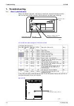
1.3.2
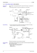
Function of main connection terminal
Terminal No.
Contents of function
Single phase 220 – 240 V 50Hz
Single phase 220 – 220 V 60Hz
Power supply and earth terminal
Connection terminal for remote controller for HRV
unit.
This terminal is used to receive information of the
indoor unit for interlocked operation.
This terminal is used to receive information when
centralized controller is connected.
Between terminal no. (J1) ~ (JC)
Used for “fresh up operation” by external input.
Between terminal no. (J2) ~ (JC)
Used for Operation / Stop by external input.
Power supply
Remote controller
Centralized control
Input from outside
J1 J2 JC
P1 P2
L N
TeS1
F1 F2
(HC0043)
Содержание VAM 350GJVE
Страница 7: ...Introduction Si71 502 vi 1 1 1 Cautions in Operation and Maintenance...
Страница 8: ...Si71 502 Introduction vii...
Страница 13: ...General Constructions Si71 502 4 General Constructions...
Страница 29: ...Maintenance Si71 502 20 Maintenance...
Страница 43: ...Circuit Operations Si71 502 34 Circuit Operations...
Страница 103: ...After sales Service Si71 502 94 Operation Manual...
Страница 106: ...Si71 502 Appendix Appendix 97 VAM1500GJVE VAM2000GJVE...
Страница 107: ...Appendix Si71 502 98 Appendix...