


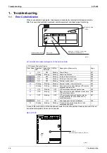


Control Functions
Si71-502
26
Control Functions
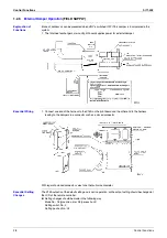
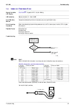
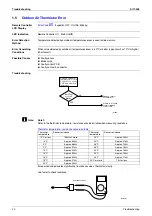
2) Link control of 2 or more groups (zone link)
Heat reclaim ventilation unit can be operated when one or more air conditioners are operating.
Allows independent operation of heat reclaim ventilation unit from VRV-system remote controller during
interim periods (direct duct connection is not allowed in this system).
Note:
With Super Wiring, units of different outdoor systems can be linked in operation.
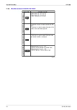
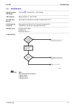
1.2.5
Field Setting, Service Mode
1. Field setting
Used for initial setting of heat reclaim ventilation unit.
2. Service mode
Used for confirmation of unit Nos. in the group and reallocation of unit Nos.
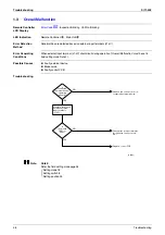
List of Field Setting and Service Mode
List of Settings
Group
1
Group
2
(HL025)
Group
3
Adapter PCB
for remote control
(KPR2A61)
Remote controller
for air conditioner
Remote controller
for air conditioner
Remote controller
for air conditioner
Mode No.
Setting
switch
No.
Description of Setting
Setting position No. (NOTE 1)
Group
settings
Individual
settings
01
02
03
04
05
06
17
27
0
Filter cleaning time setting
Approx.
2500
hours
Approx.
1250
hours
No
counting
–
–
–
1
Nighttime free cooling operation
start time (after other air
conditioners operating together
with the unit have been stopped)
Off
2 hours
4 hours
6 hours
8 hours
–
2
Pre-cool/pre-heat on/off setting
Off
On
–
–
–
–
3
Pre-cool/pre-heat time setting
30 min
45 min
60 min
–
–
–
4
Fan speed initial setting
Normal
Ultra high
–
–
–
–
5
Yes/No setting for direct duct
connection with VRV system
No duct
(Air flow
setting)
With duct
(fan off)
–
–
–
–
Setting for cold areas (Fan
operation selection for heater
thermo OFF)
–
–
No duct
With duct
Fan off
Fan L
Fan off
Fan L
6
Nighttime free cooling operation
air flow setting
High
Ultra high
–
–
–
–
7
Centralized/individual setting
Centralize
d
Individual
–
–
–
–
8
Centralized zone interlock setting
No
Yes
–
–
–
–
9
Pre-heat time extension setting
0 min
30 min
60 min
90 min
–
–
18
28
0
External signal JC/J2
Last
command
Priority on
external
input
Priority on
operation
–
–
–
1
Setting for direct Power ON
Off
On
–
–
–
–
2
Auto restart setting
Off
On
–
–
–
–
3
External damper operation
–
–
On
–
–
–
4
Indication of ventilation mode/Not
indication
Indication
No
Indication
–
–
–
–
7
Fresh up air supply/exhaust
setting
No
Indication
No
Indication
Indication
Indication
–
–
Supply
Exhaust
Supply
Exhaust
–
–
8
External input terminal function
selection (between J1 and JC)
Fresh-up
Overall
alarm
Overall
malfunction
Forced off
Fan forced
off
Air flow
increase
9
KRP50-2 output switching
selection (between 1 and 3)
Humidifying
on/off
Abnormal
–
–
–
–
Содержание VAM 350GJVE
Страница 7: ...Introduction Si71 502 vi 1 1 1 Cautions in Operation and Maintenance...
Страница 8: ...Si71 502 Introduction vii...
Страница 13: ...General Constructions Si71 502 4 General Constructions...
Страница 29: ...Maintenance Si71 502 20 Maintenance...
Страница 43: ...Circuit Operations Si71 502 34 Circuit Operations...
Страница 103: ...After sales Service Si71 502 94 Operation Manual...
Страница 106: ...Si71 502 Appendix Appendix 97 VAM1500GJVE VAM2000GJVE...
Страница 107: ...Appendix Si71 502 98 Appendix...