background image

IM 777-18 • SKYLINE OUTDOOR AIR HANDLER 38 www.DaikinApplied.com

o

peraTIon

 G

uIdelInes


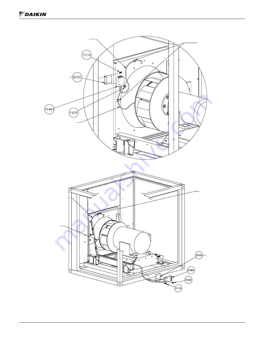
Figure 66: Direct-drive Plenum Fan Installation        

Figure 67: Fan Array Installation     

Route tube (DCX56) from the high pressure tap 

of the transmitter to the outer face of the funnel 

or the inlet panel.
Location may vary depending on fan size.

Position mounting angle as close to the 

unit drive side access door as possible 

without interfering with the door hardware 

and at eye level. Or equal to half of the 

cabinet door height.
Screw to liner or bulkhead with FS116.

Route tube (DCX56) from the low pressure tap

of the transmitter to the Piezo Ring located on

the throat of the funnel.

Secure tubing to the fan assembly

using cable-tie mount (DCX52) and

Cable-tie (DCX54) as needed.
Make sure any tubing does not 

interfere with the fan wheel.

NOTE:

Never drill or screw through

the inlet funnel.

Secure tubing to the fan assembly

using cable-tie mount (DCX52) and

Cable-tie (DCX54) as needed.
Make sure any tubing does not 

interfere with the fan wheel.

Position the mounting plate on the 

fan support angle in a location that 

allows maximum access for field wiring.
Fasten the plate to the fan support angle 

using two screws (FS116).

Route tube (DCX56) from the high pressure tap 

of the transmitter to the outer face of the funnel 

or the inlet panel.
Location may vary depending on fan size.

Route tube (DCX56) from the low pressure tap

of the transmitter to the Piezo Ring located on

the throat of the funnel.

NOTE:

Never drill or screw through

the inlet funnel.

Содержание Skyline OAH003GDAC

Страница 1: ...Installation and Maintenance Manual IM 777 17 Group Applied Air Systems Part Number IM 777 Date December 2019 Skyline Outdoor Air Handler...

Страница 2: ...tment 24 OSHPD Seismic Anchoring Mounting 26 Electrical Installation 27 Wiring 27 Operation Guidelines 29 Startup Checks 29 Before Starting the Unit 29 VFD Setup 30 Fan Startup 30 Fan Wheel Alignment...

Страница 3: ...section NOTE A special 30 Torx bit is required for assembly Identification Every shipping section includes a nameplate identifying the customer tagging information unit serial number unit order numbe...

Страница 4: ...if any moisture is present A field supplied desiccant bag may be hung in the interior of the unit to minimize corrosion in humid storage environments Do not stack sections or store anything on top of...

Страница 5: ...when supplied with VFDs Figure 1 Servicing Space Requirements Figure 2 Service Clearance for Electrical Power Devices Rigging WARNING Use all lifting points Improper lifting can cause severe personal...

Страница 6: ...it is shipped in more than one shipping section rig each section into position separately Shipping sections are provided with a connection splice joint attached to the cabinet which seals against the...

Страница 7: ...on the top two on the bottom on each side of the unit which are factory supplied in the splice kits with each unit Complete each section top and bottom before attaching additional sections Figure 8 b...

Страница 8: ...lk the bottom of the base rail at the section split This seam acts as a weep hole 5 After sections are seated tightly together add caulk to fill the seam between the roof panels at each end Slide the...

Страница 9: ...e panels Removing all flat head fasteners along the sides of a panel allow it to be removed Fan and filter sections are always provided with a service door on one side of the unit If requested on orde...

Страница 10: ...ere is no exposed insulation Field Mounting Junction Boxes and Other Components For field mounting 4 4 or smaller junction boxes to the standard panel exterior use a minimum quantity of four 3 16 diam...

Страница 11: ...s STEP 1 At the inside corner of each frame are 4 tabs 2 per side Place a leg extension over the 4 tabs as shown in Figure 18 then pull back on the leg extension locking it into place Figure 19 Repeat...

Страница 12: ...that the upper filters can rest on the lower filters Figure 22 Figure 21 Frame with Leg Extensions Installed Figure 22 Insert HEPA Filter into Frame until the Gasket Comes in Contact with the Holding...

Страница 13: ...straight to step 5 STEP 5 The prefilter holding frame should be placed directly in front of the HEPA filter as shown in Figure 27 Figure 28 Positioning of the prefilter frame STEP 6 Place a latch so t...

Страница 14: ...n Cap Screw to 1 4 of the Coupling Figure 31 Tighten until Latch and Coupling Meet Once all four corners have been tightened the HEPA filter should now be properly seated and sealed Repeat the process...

Страница 15: ...lation add the appropriate prefilter latches to the prefilter holding frame Once latches are installed place the prefilter in the frame secure with the latches and the installation is complete Repeat...

Страница 16: ...tself do not connect ductwork directly to the unit roof panel only Seal the ductwork to the opening the unit itself and to the unit roof panel to prevent moisture intrusion into the unit or building N...

Страница 17: ...EPTION For the angled economizer the fresh air and return air dampers must always be driven by separate actuators NOTE Damper blades are at full flow when open to 70 degrees Do not open blades further...

Страница 18: ...e full open position before the fan is started Do not start a fan with the damper located at the inlet with the damper fully or partially closed This can cause airflow vibration and sound problems tha...

Страница 19: ...40 Detail A 2 Follow the instructions to attach rigging and lift the vestibule vertically Remove the shipping pallet 3 Apply a continuous bead of caulking to the vertical flange of the vestibule roof...

Страница 20: ...AIR HANDLER 20 www DaikinApplied com Mechanical Installation Figure 42 Caulking the Vestibule Roof Cap Figure 43 Detail of Mounting Screws Figure 44 Additional Caulking UNIT TO VESTIBULE SPLICE DETAIL...

Страница 21: ...iping see Figure 45 Steam supply and steam return connections typically are male NPT iron pipe and are labeled on the end panel of coil section Connections extend through the coil section end panel Wh...

Страница 22: ...rtup admit steam to coil ten minutes before admitting outdoor air Close fresh air dampers if steam supply pressure falls below the minimum specified Pipe Chases Follow the these guidelines when routin...

Страница 23: ...i Low Pressure to 25 psi 5GA or 8GA coils Note that the addition of a vacuum breaker to permit the coil to drain during shutdown 5TA 8TA or 5HA coils Conden sate is lifted to overhead return main 5JA...

Страница 24: ...re to be heated by a hot water coil carefully design the system to provide thorough mixing before air enters the coil To prepare coils for winter operation See Winterizing Water Coils on page 69 Drain...

Страница 25: ...tom Horz H Downblast H Upblast H Unit Sizes 003 035 1 3 75 3 75 4 25 2 4 25 3 75 4 25 3 4 25 3 75 4 25 4 3 75 3 75 4 25 Unit Sizes 040 090 1 6 00 6 75 6 75 2 6 50 6 75 6 75 3 6 50 6 75 6 75 4 6 00 6 7...

Страница 26: ...ical Installation Figure 50 Removing Motor Behind Shipping Brackets Figure 51 Removing Motor Beside Shipping Brackets Figure 52 Plenum Fan Typical Shipping Brackets Shipping hold down nut and bolt Rem...

Страница 27: ...frame are to be field drilled Any mounting hardware is to be field supplied Table 6 OSHPD Mounting Attachment Method SDS Attachment System by Others Spacing System Bolted attachment to steel Figure 52...

Страница 28: ...unit must also penetrate the drip pan If holes are cut in the drip pan seal them to prevent moisture leakage Figure 56 Electrical Conduit Location Electrical service to each fan must correspond to th...

Страница 29: ...s can result in uneven airflow that can cause performance sound and vibration problems that can lead to failure Provided that the fan is capable of running fast enough the motor is sized appropriately...

Страница 30: ...arranty Before entering fan section make sure that fan electrical power source is disconnected and locked in the OFF position 1 Check that the unit is completely and properly installed with ductwork c...

Страница 31: ...48 Hours of Operation 1 Disconnect and lock electrical power source 2 Check tightness of all bearing wheel and sheave setscrews or capscrews See Table 14 on page 34 3 Recheck belt tension and adjust...

Страница 32: ...nlet Funnel Relationship 13 to 36 Belt Drive Plenum Fan Wheel Funnel Parameters in mm Size in A B C 13 0 25 6 35 0 91 23 11 3 50 88 9 15 0 25 6 35 0 91 23 11 3 50 88 9 16 0 25 6 35 0 91 23 11 3 50 88...

Страница 33: ...Table 12 Wheel to Inlet Funnel Relationship Direct Drive Class II fans Fan Size in Overlap in mm 11 0 25 6 35 12 0 25 6 35 15 0 25 6 35 16 0 38 9 65 18 0 38 9 65 20 0 41 10 41 22 0 45 11 43 24 0 50 12...

Страница 34: ...ass II Plenum Fans Only Fan Size Setscrew Size Torque ft lb Aluminum Steel 11 12 13 3 8 19 2 N A 15 3 8 19 2 N A 16 3 8 19 2 N A 18 3 8 19 2 N A 20 3 8 19 2 N A 22 3 8 19 2 N A 24 3 8 19 2 N A 27 3 8...

Страница 35: ...st fan motor the block off plate is installed on the non functional fan to prevent air re circulation This is designed to be a temporary measure unit this fan and or motor is replaced After fan and or...

Страница 36: ...A Inlet funnel throat area square feet from Table 17 and Table 19 P The differential in static pressure from the piezometer ring and the inlet pressure tap inches w g Air density pounds mass cubic fo...

Страница 37: ...ensity Method Daikin Piezo Ring DDPL Size Free Inlet F Ducted Inlet F Area A 12 1004 66 1016 46 0 344 15 1261 99 1260 20 0 439 16 1526 96 1572 35 0 552 18 1675 69 1672 77 0 721 20 2117 33 2110 61 0 86...

Страница 38: ...el Secure tubing to the fan assembly using cable tie mount DCX52 and Cable tie DCX54 as needed Make sure any tubing does not interfere with the fan wheel NOTE Never drill or screw through the inlet fu...

Страница 39: ...e control panel can be ordered for remote mounting For remote mounted panels the control wiring for the individual fans will be provided however the control wiring to connect the final fan to the cont...

Страница 40: ...Operation Guidelines Figure 69 Single Fan Control Panel High Voltage Wiring in red Low Voltage Wiring in blue Figure 70 Required Molex Plug and Crimp Terminals Figure 71 Molex Plug Crimp Terminal Loca...

Страница 41: ...OOR AIR HANDLER Figure 73 Control Signal Figure 74 High Voltage Wiring Figure 75 Gen 2 Figure 76 YY Figure 77 Block Off Plate Installation YY Figure 78 Gen 3 003 BLOCK OFF PLATE KIT PART NO FAN SIZE 9...

Страница 42: ...he following equation is used to measure the flow for non standard density ACFM C1 A P where A Inlet funnel throat area square feet from Table 21 P The differential in static pressure from the piezome...

Страница 43: ...imum rpm Class I 2077 1875 1691 1479 1328 1209 1073 Maximum rpm Class Il 2703 2413 2199 1928 1730 1579 1401 Table 24 Operating Limits Belt Drive Plenum Fans Fan Operating Limits Belt Drive Plenum Fans...

Страница 44: ...e contributes to premature fan and motor bearing failure Monitor overall vibration levels every six months of operation An increase in levels is an indication of potential trouble Vibration Causes 1 W...

Страница 45: ...NING All field gas piping must be pressure leak tested prior to operation NEVER use an open flame to check for leaks Use a soap solution or other leak detecting solution Gas pressure to appliance cont...

Страница 46: ...on flue gases Gas supply piping and connections Condensate Drain Lines WARNING Failure to connect condensate drains can result in accumulation of condensate during heater operation and result in hazar...

Страница 47: ...by flame sensor the spark is shut off immediately and gas valve s and combustion blower remain energized 10 During heating operation the thermostat pressure switch and main burner flame are constantly...

Страница 48: ...1 2 TR1 TIMER RELAY TERMINAL CONNECTION 1 2 3 4 6 AIR SWITCH HI 3 ORG ORG YEL BLU TIMER RELAY TR1 090LH15 Factory Jumper 4 115 VAC BLK WHT BLU External Safety Interlocks YEL GRY PUR 40VA ORG ORG ROLL...

Страница 49: ...l open or close modulating the gas input between low and mid fire 14 If the signal is 5 1 VDC or higher the SC40 relay R1 is de energized and ID Fan goes to high speed 15 Provided the High Air Switch...

Страница 50: ...24V APS PSW T Stat Sense 3 PUR HI LIMIT PUR APS 1 AIR SWITCH LO ORG ORG ORG ORG ROLL OUT SWITCH ROLL OUT SWITCH 2 Maxitrol SC40 T1 T2 T3 T4 T5 T6 T7 T8 COM T9 HAPS EST R1 24V E Valve T10 T11 T1 T2 T S...

Страница 51: ...lit if ID Fan pressure is sufficient to close APS 2 The modulating valve will be powered proportional to the analog input voltage signal and modulating gas input from 10 to 30 of total heater input 1...

Страница 52: ...or within 10 seconds the spark and gas valve will be de energized A 15 second interpurge period begins and the combustion blower continues to run After the inter purge period another ignition trial wi...

Страница 53: ...4 T3 T9 T8 T12 T13 T11 T10 PUR W PUR W T2 T1 5 6 RED W RED W 0 10 VDC Input RED BLK BLK RED M420 Mod Valve BLK YEL 24V R C 3 4 40VA BLU XFMR 2 BLU WHT FLAME SENSOR ROR IGNITER SPARK T2 T1 SC30 SM2AN P...

Страница 54: ...eration Additional slave furnaces have two stage controls which are activated by relays on the staging control to meet higher heating requirements As slave units are brought on line the modulating hea...

Страница 55: ...7 8 11 6 9 24V COM 120V 8 Provide Disconnect and Overload Protection as required 120V 1 60 5 15 BLK BLK BLK 1 1 1 2 2 2 5 7 7 3 120 V Alarm Output BK W 6 4 2 1 0 4 2 1 0 BLOWER SCEBM 2 13 WHT 14 RED...

Страница 56: ...rol Panel terminal N Factory Wiring Customer Wiring Fuse 24V 24V BLU BLU T1 T2 System Heat Enable Contact Customer Safety Interlocks WC HDR HXT FDP 12A VCB 1M 3SL Distribution Panel Terminal Connectio...

Страница 57: ...talled in accordance with the applicable provincial regulations Furthermore this document is not to relinquish the responsibility of the installer from the correct application of the equipment nor the...

Страница 58: ...can cause property damage injury or death Read the installation operating and maintenance instructions thoroughly before installing or servicing this equipment The use and storage of gasoline or othe...

Страница 59: ...0 0 0 0 0 M s e t t i m e d a t e N O P C O 0 0 0 oF L o a d i n g s e l f t e s t p l e a s e w a i t B u r n e r I n p u t S i g n a l 0 H e a t e r E n a b l e I n p t O F F B u r n e r E n a b l...

Страница 60: ...irst screen see 3 14 The Alarm button will light up red when the unit is in alarm 15 To view the alarms a Push the Alarm Bell button and then scroll using the up and down arrow buttons to view all the...

Страница 61: ...BMS Address Description Direction Variable name 9 Profile pressure 1000 R profilePressure 95 Current minute R CURRENT_MINUTE 96 Current hour R CURRENT_HOUR 97 Current year R CURRENT_YEAR 98 Current m...

Страница 62: ...Fan Motor Bearings Mfr Grease NEMA Size Amount to Add oz Texaco Polystar or Polyrex EM Exxon Mobil or Rykon Premium 2 or Penzoil Pen 2 Lube 56 to 140 0 08 140 0 15 180 0 19 210 0 30 250 0 47 280 0 61...

Страница 63: ...is operating Moving parts and strong suction forces can cause severe personal injury or death Upon completion of the air balance replace the variable pitched motor sheave with a properly sized fixed...

Страница 64: ...ave Adjustment LVP Variable Speed Sheaves Mounting 1 Slide sheave on motor shaft so that the side of the sheave with setscrew A is next to the motor when setscrew A is in the hub or barrel of the shea...

Страница 65: ...ne of the driven sheave See Figure 88 2 Verify that all setscrews are torqued to the values shown in Table 35 before starting drive Check setscrew torque and belt tension after 24 hours of service Adj...

Страница 66: ...in lbs Seating torque in lbs Seating torque in lbs Seating torque in lbs Seating torque in lbs Length L in lbs Seating torque in lbs 1 4 20NC 150 12 5 100 87 7 3 3 16 50 5 16 11NC 305 25 4 200 165 13...

Страница 67: ...can cause slippage 5 Inspect V drive on a periodic basis Adjust tension if the belt is slipping Do not apply belt dressing This can damage the belt and cause early failure Tension Measurement Procedur...

Страница 68: ...ilter gauge is used the prefilters can be removed to check the pressure drop of the final filters Figure 95 Filter Gauge Table 37 Filter Pressure Drops Bag filters DriPak 2000 Efficiency 45 65 85 95 R...

Страница 69: ...small amount of antifreeze solution remaining in the coil must always be concentrated enough to prevent freeze up NOTE Carefully read instructions for mixing antifreeze solution used Some products ha...

Страница 70: ...all piping and remove the brass plugs for the vents and drains located in the connections 2 Remove all screws and remove the access panel 3 Remove the screws holding the coil in place 4 Lift and pull...

Страница 71: ...nce the coil is in place bolt the coil to the section 4 Caulk the mounting surface of the steel plate and install the plate on the coils 5 Caulk the mounting surface of the drain trough and install th...

Страница 72: ...erial Procedure Defective material may not be returned without permission of authorized factory service personnel of Daikin in Minneapolis Minnesota 763 553 5330 A Return Goods tag must be included wi...

Страница 73: ...____ State _________________________________ Purchasing contractor ___________________________________________________________________________________________ City ____________________________________...

Страница 74: ...N A J Fill the drain pan Does water drain freely Yes No N A K Is the unit mounted level Yes No N A II FAN DATA A Check rotation of supply fan s Yes No N A B Voltage at supply fan motor s 1 2_________...

Страница 75: ...urn fan motor amp draw s per phase L1 _____________ L2 _____________ L3 _____________ Fan array units only L1 _____________ L2 _____________ L3 _____________ L1 _____________ L2 _____________ L3 _____...

Страница 76: ...2 Stage 3 Stage 4 Stage 5 Stage 6 Phase L1 ___________ ____________ ____________ ___________ ___________ ____________ Phase L2 ___________ ____________ ____________ ___________ ___________ __________...

Страница 77: ...TEST START Specifications For gas see Forced Draft Gas Burner Installation and Maintenance Bulletin IM 684 and IM 685 A Gas Furnace Model no __________________ B Gas Burner Model no _________________...

Страница 78: ..._______________________ Startup date ___________________________ Return completed form by mail to Daikin Warranty Department 13600 Industrial Park Boulevard Minneapolis MN 55441 or by email to AAH Wty...

Страница 79: ..._______ 2 How would you rate the overall appearance of the product i e paint fin damage etc Excellent Good Fair Poor 3 Did all sections of the unit fit together properly Yes No N A 4 Did the cabinet h...

Страница 80: ...nt to its standard terms and conditions of sale including Limited Product Warranty Consult your local Daikin Applied Representative for warranty details To find your local Daikin Applied Representativ...

Отзывы: