manualshive.com logo in svg
background image

INSTALLATION MANUAL

R410A Split Series

MODEL

RXLG25L2V1B
RXLG35L2V1B
RXL35K2V1B
RXL25J3V1B
RXL35J3V1B
RXL20K3V1B
RXL25K3V1B
RXLG25K3V1B
RXLG35K3V1B

Содержание RXL20K3V1B

Страница 1: ...INSTALLATION MANUAL R410A Split Series MODEL RXLG25L2V1B RXLG35L2V1B RXL35K2V1B RXL25J3V1B RXL35J3V1B RXL20K3V1B RXL25K3V1B RXLG25K3V1B RXLG35K3V1B...

Страница 2: ...y es valorado positivamente por B de acuerdo con el Certificado C 06 Nota delineato nel A e giudicato positivamente da B secondo l Certificato C 07 A B C 08 Nota tal como estabelecido em A e com o par...

Страница 3: ...A y es valorado positivamente por B de acuerdo con el Certificado C 06 Nota delineato nel A e giudicato positivamente da B secondo l Certificato C 07 A B C 08 Nota tal como estabelecido em A e com o p...

Страница 4: ...o positivamente por B de acuerdo con el Certificado C 06 Nota delineato nel A e giudicato positivamente da B secondo l Certificato C 07 A B C 08 Nota tal como estabelecido em A e com o parecer positiv...

Страница 5: ...abnormal heat build up or fire When wiring the power supply and connecting the wiring between the indoor and outdoor units position the wires so that the control box lid can be securely fastened Impr...

Страница 6: ...not place under the unit anything which must be kept away from moisture NOTE Cannot be installed hanging from ceiling or stacked CAUTION When operating the air conditioner in a low outdoor ambient tem...

Страница 7: ...top valve cover into the outdoor unit to install Tighten the screws Stop valve cover O D 9 5mm Gas pipe Liquid pipe O D 6 4mm 20g m 15m 20m Max allowable length Max allowable height Additional refrige...

Страница 8: ...fix the unit securely by means of the foundation bolts Prepare four sets of M8 or M10 foundation bolts nuts and washers each which are available on the market It is best to screw in the foundation bol...

Страница 9: ...orque wrenches when tightening the flare nuts to prevent damage to the flare nuts and gas leakage Align the centres of both flares and tighten the flare nuts 3 or 4 turns by hand Then tighten them ful...

Страница 10: ...n side of charging hose which comes from gauge manifold to gas stop valve s service port 2 Fully open gauge manifold s low pressure valve Lo and completely close its high pressure valve Hi High pressu...

Страница 11: ...id piping and to provide insulation dimensions as below 3 Use separate thermal insulation for gas and liquid refrigerant pipes Gas side Liquid side Gas pipe thermal insulation Liquid pipe thermal insu...

Страница 12: ...n 1 Check that the main power supply is turned OFF Turn it OFF if has not been turned OFF 2 Remove the stop valve cover 3 Disconnect the selective connector for standby electricity saving 4 Turn ON th...

Страница 13: ...AUTION 1 When pressing the switch do not touch the terminal block It has a high voltage so doing so may cause electric shock 2 After closing the liquid stop valve close the gas stop valve within three...

Страница 14: ...notes mentioned below when wiring to the power supply terminal board Precautions to be taken for power supply wiring Use a round crimp style terminal for connection to the power supply terminal board...

Страница 15: ...5 C6 C119 Capacitor DB1 DB2 DB3 Diode bridge E1H Heater FU1 FU2 FU3 FU4 FU5 Fuse FU6 Field fuse IPM1 IPM2 Intelligent power module L Live L1 Coil L1R Reactor M1C Compressor motor M1F Fan motor MRCW MR...

Страница 16: ...requires a small amount of power in its standby mode If the system is not to be used for some time after installation shut off the circuit breaker to eliminate unnecessary power consumption If the ci...

Страница 17: ......

Страница 18: ......

Страница 19: ......

Страница 20: ...3P291651 8R 2013 12 Copyright 2013 Daikin...
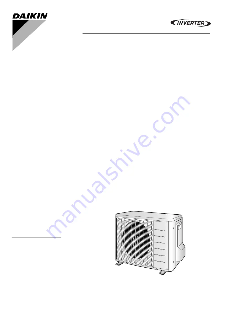
Отзывы: