
53
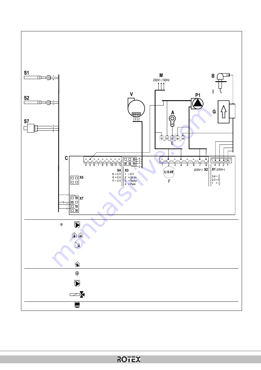
10.3
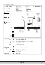
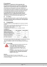
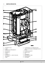
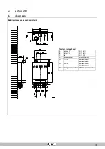
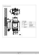
Diagramme électrique
A
Connexion de terre de
l'échangeur
F
Fusible (3.15 A T)
P1
Pompe CH
S7
Capteur de pression d'eau
CH
B
Hotte d'allumage
G
Bloc de gaz + module
d'allumage
V
Ventilateur
C
Régulateur de chaudière
I
Broche
d'allumage/d'ionisation
S1
Capteur d'eau de
sortie
E
Connexions de terre
M
Alimentation électrique
S2
Capteur de retour
Connecteur X4
24 V=
5 -
Pompe (5=signal PWM (rouge), E=terre)
6-7
Marche/arrêt thermostat d'ambiance
(0,1A-24Vcc)
et/ou thermostat gel
8-9
Capteur extérieur
(12k ohm / 25°C)
9-10
Capteur du ballon
(12k ohm / 25°C)
11-12
Thermostat d'ambiance OpenTherm
(6-7 doit être ouvert)
Connecteur X2
230V
~
2-4
Alimentation secteur de 230 V (2=L (marron), 4=N (bleu))
7-8
Pompe CH
(8=L (marron), 7=N (bleu))
3-5-6
Vanne trois voies pour ballon externe
(3=L (marron), 5=commutateur (noir), 6=N (bleu)
(par ex., EK3WV1AA)
Connecteur X5
Interface ordinateur
Содержание Rotex GW-30 H12
Страница 1: ...ROTEX 4P381271 88527701 02 2016 4P381271 88527701 02 2016...
Страница 29: ...30...
Страница 80: ...30...
Страница 132: ...31...
Страница 184: ...31...
Страница 236: ...31...
Страница 287: ...ROTEX Heating Systems GmbH 30...
Страница 339: ...30...
Страница 392: ...31...
Страница 416: ...ROTEX 008 1548899_00 88527703 05 2018...