Troubleshooting by Remote Controller
Si33-105
150
Troubleshooting R407C PLUS Series Heat Recovery System
2.4
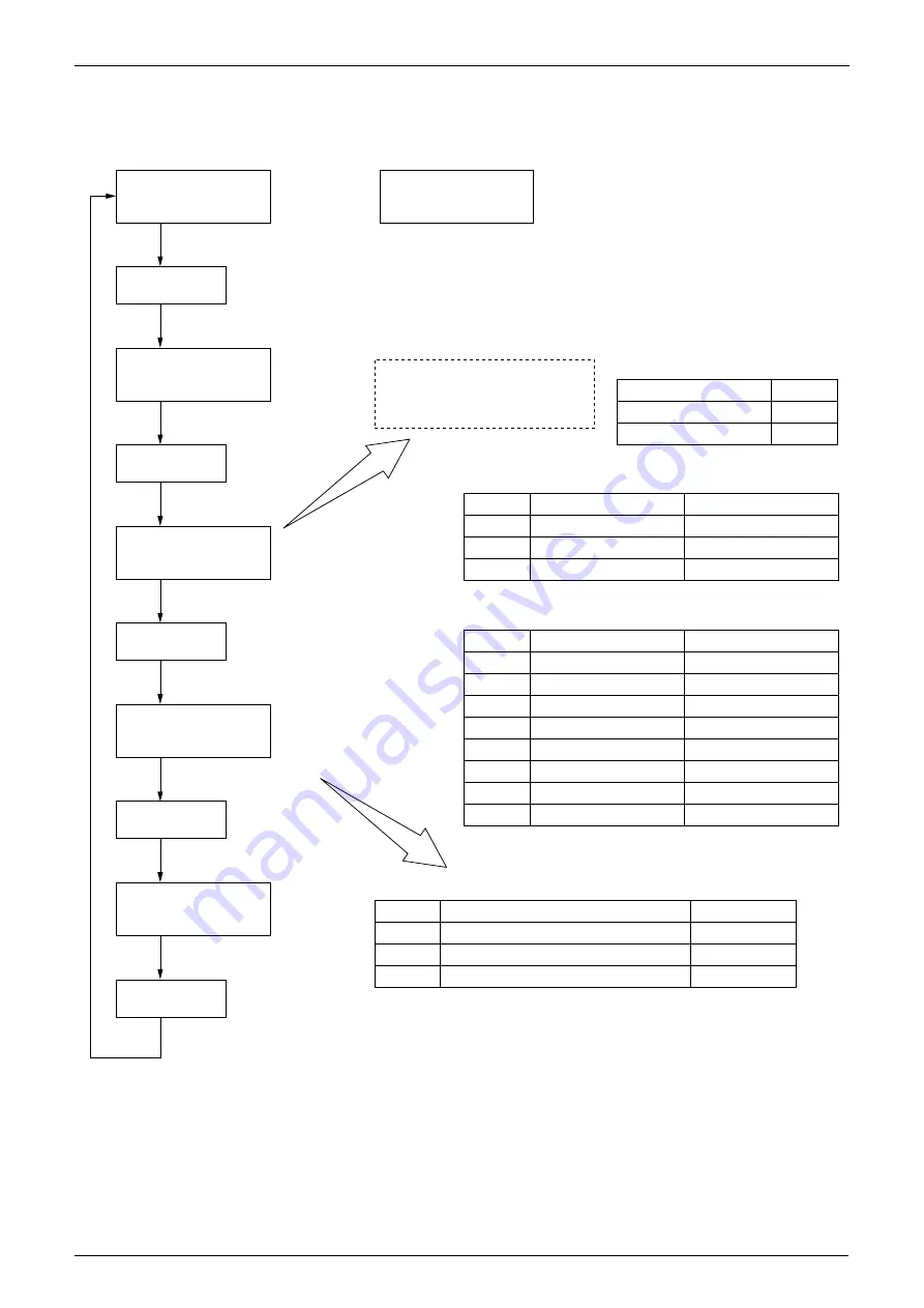
Operation of The Remote Controller’s Inspection / Test
Operation Button
Inspection/test
operation
Example model
FXYCP25K
FXYFP63K
Example of capacity code display
Display
028
071
Product classification
VRV system
VRV system
VRV system
Display
1
2
F
Indoor unit system code
System classification
(VAV indoor unit)
Outdoor air intake
Standard indoor unit
Type
Wall mounted
Double flow
Corner
Multi flow
Ceiling suspended
Built-in
Floor standing
Concealed ceiling duct
Display
A
C
E
F
H
J
L
U
Indoor unit type code
Model
FXYAP
FXYCP
FXYKP
FXYFP
FXYHP
FXYSP
FXYLP
FXYMP
Type
VRV System Inverter K Series
R407C VRV PLUS Series
R407C VRV PLUS Heat recovery Series
Display
A A 1
A A 3
A 9 3
Outdoor model code
Model
RSXYP
RSXYP
RSEYP
Unit
Malfunction code
Inspection
Normal display (No display)
0
L 0
Malfunction code blinks when a malfunction occurs.
Unit
Malfunction code
Inspection
Inspection mode
Push the button.
Inspection/test
operation
Push the button.
Inspection/test
operation
Push the button.
Inspection/test
operation
Push the button.
Inspection/test
operation
Push the button.
0
L 0
Indoor unit model code display
0 7 1
F C 2
Outdoor unit model code display
– – –
A A 1
Test operation
Test operation mode
Capacity code
Indoor unit system code
Indoor unit type code
Progression code
0 7 1...
F...
C...
2...
(VF019)
Содержание R407C PLUS
Страница 1: ...System R407C PLUS Series Heat Recovery System Si33 105 Service Manual ...
Страница 11: ...Introduction Si33 105 x ...
Страница 41: ...Specifications Si33 105 30 Specifications R407C PLUS Series Heat Recovery System ...
Страница 147: ...Test Operation Si33 105 136 Test Operation R407C PLUS Series Heat Recovery System ...
Страница 158: ...Si33 105 Troubleshooting by Remote Controller Troubleshooting R407C PLUS Series Heat Recovery System 147 ...
Страница 160: ...Si33 105 Troubleshooting by Remote Controller Troubleshooting R407C PLUS Series Heat Recovery System 149 ...
Страница 229: ...Troubleshooting OP Unified ON OFF Controller Si33 105 218 Troubleshooting R407C PLUS Series Heat Recovery System ...
Страница 232: ...Si33 105 Piping Diagram Appendix R407C PLUS Series Heat Recovery System 221 RSEYP24 26 28 30KJY1 3D031938 ...
Страница 234: ...Si33 105 Piping Diagram Appendix R407C PLUS Series Heat Recovery System 223 BSVP250KJV1 4D014499A ...
Страница 237: ...Wiring Diagram Si33 105 226 Appendix R407C PLUS Series Heat Recovery System RSEYP24 26 28 30KJY1 3D031467 ...
Страница 238: ...Si33 105 Wiring Diagram Appendix R407C PLUS Series Heat Recovery System 227 2 2 BS Unit 3D014829B ...
Страница 240: ...Si33 105 Wiring Diagram Appendix R407C PLUS Series Heat Recovery System 229 FXYFP32 40 50 63 80 100 125KVE 3D020238B ...
Страница 241: ...Wiring Diagram Si33 105 230 Appendix R407C PLUS Series Heat Recovery System FXYCP20 25 32 63KV1 DU229 5139C ...
Страница 242: ...Si33 105 Wiring Diagram Appendix R407C PLUS Series Heat Recovery System 231 FXYCP40 50 80 125KV1 DU230 522C ...
Страница 243: ...Wiring Diagram Si33 105 232 Appendix R407C PLUS Series Heat Recovery System FXYKP25 32 40 63KV1 DU227 544C ...
Страница 244: ...Si33 105 Wiring Diagram Appendix R407C PLUS Series Heat Recovery System 233 FXYSP20 25 32 40 50 63KV1 DU227 545E ...
Страница 245: ...Wiring Diagram Si33 105 234 Appendix R407C PLUS Series Heat Recovery System FXYSP80 100 125KV1 DU230 519D ...
Страница 246: ...Si33 105 Wiring Diagram Appendix R407C PLUS Series Heat Recovery System 235 FXYMP40 50 63 80 100 125KV1 DU229 5140C ...
Страница 247: ...Wiring Diagram Si33 105 236 Appendix R407C PLUS Series Heat Recovery System FXYMP200 250KV1 3D011012B ...
Страница 248: ...Si33 105 Wiring Diagram Appendix R407C PLUS Series Heat Recovery System 237 FXYHP32 63 100KV1 DU228 531C ...
Страница 249: ...Wiring Diagram Si33 105 238 Appendix R407C PLUS Series Heat Recovery System FXYAP20 25 32 40 50 63KV1 DU221 561F ...
Страница 263: ...Si33 105 iv Index ...


