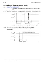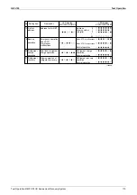
Outline of Control (Indoor Unit)
Si33-105
98
Function R407C PLUS Series Heat Recovery System
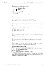
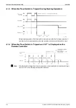
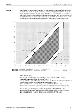
4.1.3 When the Float Switch is Tripped During Heating Operation:
During heating operation, if the float switch is not reset even after the 5 minutes operation, 5
seconds stop, 5 minutes operation cycle ends, operation continues until the switch is reset.
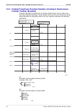
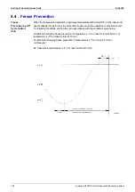
4.1.4 When the Float Switch is Tripped and “AF” is Displayed on the
Remote Controller:
Note:
If the float switch is tripped five times in succession, a drain malfunction is determined to have
occurred. “AF” is then displayed as operation continues.
Содержание R407C PLUS
Страница 1: ...System R407C PLUS Series Heat Recovery System Si33 105 Service Manual ...
Страница 11: ...Introduction Si33 105 x ...
Страница 41: ...Specifications Si33 105 30 Specifications R407C PLUS Series Heat Recovery System ...
Страница 147: ...Test Operation Si33 105 136 Test Operation R407C PLUS Series Heat Recovery System ...
Страница 158: ...Si33 105 Troubleshooting by Remote Controller Troubleshooting R407C PLUS Series Heat Recovery System 147 ...
Страница 160: ...Si33 105 Troubleshooting by Remote Controller Troubleshooting R407C PLUS Series Heat Recovery System 149 ...
Страница 229: ...Troubleshooting OP Unified ON OFF Controller Si33 105 218 Troubleshooting R407C PLUS Series Heat Recovery System ...
Страница 232: ...Si33 105 Piping Diagram Appendix R407C PLUS Series Heat Recovery System 221 RSEYP24 26 28 30KJY1 3D031938 ...
Страница 234: ...Si33 105 Piping Diagram Appendix R407C PLUS Series Heat Recovery System 223 BSVP250KJV1 4D014499A ...
Страница 237: ...Wiring Diagram Si33 105 226 Appendix R407C PLUS Series Heat Recovery System RSEYP24 26 28 30KJY1 3D031467 ...
Страница 238: ...Si33 105 Wiring Diagram Appendix R407C PLUS Series Heat Recovery System 227 2 2 BS Unit 3D014829B ...
Страница 240: ...Si33 105 Wiring Diagram Appendix R407C PLUS Series Heat Recovery System 229 FXYFP32 40 50 63 80 100 125KVE 3D020238B ...
Страница 241: ...Wiring Diagram Si33 105 230 Appendix R407C PLUS Series Heat Recovery System FXYCP20 25 32 63KV1 DU229 5139C ...
Страница 242: ...Si33 105 Wiring Diagram Appendix R407C PLUS Series Heat Recovery System 231 FXYCP40 50 80 125KV1 DU230 522C ...
Страница 243: ...Wiring Diagram Si33 105 232 Appendix R407C PLUS Series Heat Recovery System FXYKP25 32 40 63KV1 DU227 544C ...
Страница 244: ...Si33 105 Wiring Diagram Appendix R407C PLUS Series Heat Recovery System 233 FXYSP20 25 32 40 50 63KV1 DU227 545E ...
Страница 245: ...Wiring Diagram Si33 105 234 Appendix R407C PLUS Series Heat Recovery System FXYSP80 100 125KV1 DU230 519D ...
Страница 246: ...Si33 105 Wiring Diagram Appendix R407C PLUS Series Heat Recovery System 235 FXYMP40 50 63 80 100 125KV1 DU229 5140C ...
Страница 247: ...Wiring Diagram Si33 105 236 Appendix R407C PLUS Series Heat Recovery System FXYMP200 250KV1 3D011012B ...
Страница 248: ...Si33 105 Wiring Diagram Appendix R407C PLUS Series Heat Recovery System 237 FXYHP32 63 100KV1 DU228 531C ...
Страница 249: ...Wiring Diagram Si33 105 238 Appendix R407C PLUS Series Heat Recovery System FXYAP20 25 32 40 50 63KV1 DU221 561F ...
Страница 263: ...Si33 105 iv Index ...


