background image

15

 | 

Piping installation

Installer and user reference guide

99

LREN8~12A7 + LRNUN5A7
CO₂ ZEAS outdoor unit and capacity up unit
4P704142-1 – 2022.08

2

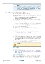
Afterwards, vacuum dry the unit to –100.7 kPaG (-1.007 bar gauge) or less for
at least 1 hour.

3

Repeat vacuum destruction and vacuum drying if the pressure does not reach
–100.7 kPaG (-1.007 bar gauge) or less.

4

Leave the unit for more than 1 hour with a vacuum pressure of –100.7 kPaG
(-1.007 bar gauge) or less. On the vacuum gauge, check if the pressure does
not increase.

15.5 Insulating the refrigerant piping

After finishing the leak test and vacuum drying, the piping must be insulated. Take
into account the following points:

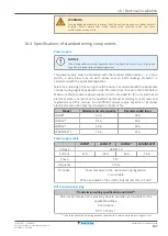
Be sure to insulate the liquid and gas piping (for all units).

For  liquid  and  gas  piping:  Use  heat  resistant  polyethylene  foam  which  can
withstand a temperature of 70°C.

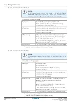
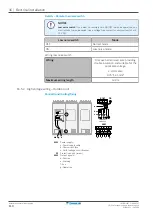
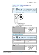
Insulation thickness

Take the following into account when determining the insulation thickness:

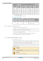
Piping

Minimum temperature during

operation

Liquid piping

0°C

Gas piping

–40°C

Depending  on  your  local  weather  conditions,  you  may  need  to  increase  the
thickness  of  the  insulation.  If  the  ambient  temperature  exceeds  30°C  and  the
humidity exceeds 80%.

Increase the thickness of the liquid piping with ≥5 mm

Increase the thickness of the gas piping with ≥20 mm

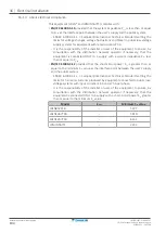
Insulation sealing

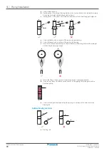
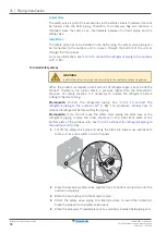
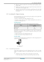
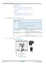
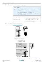
To prevent rain and condensed water entering the unit, add a sealing between the
insulation and the front panel of the unit.

a

a

a

a

b

b

a

Sealing material

b

Front panel

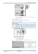
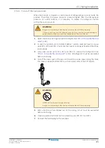
15.5.1 To insulate the gas stop valve

The gas pipes and stop valve can reach temperatures as low as –40°C. For safety
reasons,  it  is  therefore  necessary  to  insulate  these  parts  as  soon  as  all  tests  are
done.

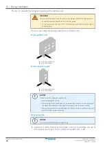
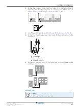
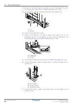
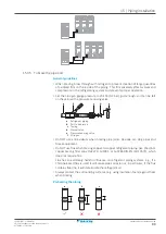
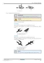
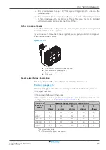
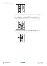
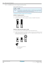
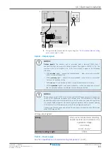
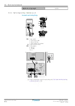
1

Install the accessory insulation tube around the gas stop valve's body.

Position the accessory insulation tube around the gas stop valve's body.
Содержание LREN8A7Y1B

Страница 1: ...Installer and user reference guide CO ZEAS outdoor unit and capacity up unit LREN8A7Y1B LREN10A7Y1B LREN12A7Y1B LRNUN5A7Y1...

Страница 2: ...nce and service 33 8 1 Maintenance before a long stop period 33 8 2 Maintenance after a long stop period 33 8 3 About the refrigerant 34 8 4 Recommended maintenance and inspection 34 9 Troubleshooting...

Страница 3: ...cting the refrigerant piping 83 15 3 2 Precautions when connecting the refrigerant piping 84 15 3 3 To cut off the spun pipe ends 85 15 3 4 To connect the refrigerant piping to the outdoor unit 86 15...

Страница 4: ...issioning 129 20 4 About the test run 130 20 5 To perform a test run 7 segment display 130 20 5 1 Test run checks 131 20 5 2 Correcting after abnormal completion of the test run 133 20 6 Operating the...

Страница 5: ...stallation and operation instructions Format Paper in the box of the outdoor unit Installer and user reference guide of the outdoor unit Preparation of the installation reference data Detailed step by...

Страница 6: ...r 2 1 1 Meaning of warnings and symbols DANGER Indicates a situation that results in death or serious injury DANGER RISK OF ELECTROCUTION Indicates a situation that could result in electrocution DANGE...

Страница 7: ...G SCALDING Do NOT touch the refrigerant piping water piping or internal parts during and immediately after operation It could be too hot or too cold Give it time to return to normal temperature If you...

Страница 8: ...department police and hospital Name address and day and night telephone numbers for obtaining service In Europe EN378 provides the necessary guidance for this logbook 2 2 2 Installation site Provide s...

Страница 9: ...tching device only auxiliary devices approved by the manufacturer are used in the duct work air inlet AND outlet are connected directly to the same room by ducting Do NOT use spaces such as a false ce...

Страница 10: ...trogen to perform a gas leak detection NOTICE To avoid compressor breakdown do NOT charge more than the specified amount of refrigerant When the refrigerant system is to be opened refrigerant MUST be...

Страница 11: ...touch electrical components For the location of the terminals see the wiring diagram Do NOT touch electrical components with wet hands Do NOT leave the unit unattended when the service cover is remov...

Страница 12: ...o NOT connect wiring of different thicknesses to the power terminal block slack in the power wiring may cause abnormal heat When connecting wiring which is the same thickness do as shown in the figure...

Страница 13: ...kin including all documents listed in Documentation set and in addition comply with applicable legislation and are performed by qualified persons only In Europe and areas where IEC standards apply EN...

Страница 14: ...k detection see the installation manual of the indoor units WARNING In case of mechanical ventilation take care the ventilated air is exhausted to the outdoor space and NOT into another closed area WA...

Страница 15: ...easures See To determine the minimum number of appropriate measures 463 CAUTION If the safety valve operates inside the unit CO2 gas may concentrate inside the casing of the outdoor unit Therefore you...

Страница 16: ...ses If the unit is installed indoors for example in a machine room ALWAYS use a portable CO2 detector If the front panel is open ALWAYS beware of the rotating fan The fan will continue rotating for a...

Страница 17: ...ling a safety valve ALWAYS add enough support to the valve An activated safety valve is under high pressure If not installed securely the safety valve may cause damage to the piping or the unit CAUTIO...

Страница 18: ...th sharp edges or piping particularly on the high pressure side Do NOT use taped wires extension cords or connections from a star system They can cause overheating electrical shock or fire Do NOT inst...

Страница 19: ...anel is open ALWAYS beware of the rotating fan The fan will continue rotating for a while even after the power switch has been turned off WARNING After charging refrigerant keep the power supply and o...

Страница 20: ...ature conditions When internal pressure rises the outdoor unit can operate by itself to reduce the internal pressure even if no indoor unit is operating CAUTION Do NOT insert fingers rods or other obj...

Страница 21: ...the mains Turn off the respective circuit breaker When a safety device was activated stop the unit and find out why the safety device was activated before resetting it NEVER shunt safety devices or ch...

Страница 22: ...For the user Installer and user reference guide 22 LREN8 12A7 LRNUN5A7 CO ZEAS outdoor unit and capacity up unit 4P704142 1 2022 08 For the user...

Страница 23: ...s with reduced physical sensory or mental capabilities or lack of experience and knowledge if they have been given supervision or instruction concerning use of the appliance in a safe way and understa...

Страница 24: ...authority Batteries are marked with the following symbol This means that the batteries may NOT be mixed with unsorted household waste If a chemical symbol is printed beneath the symbol this chemical s...

Страница 25: ...iciency ventilate the room sufficiently if equipment with burner is used together with the system CAUTION Do NOT operate the system when using a room fumigation type insecticide Chemicals could collec...

Страница 26: ...shock and injury WARNING 12 MPa System contains refrigerant under very high pressure The system MUST be serviced by qualified persons ONLY WARNING NEVER replace a fuse with a fuse of a wrong ampere ra...

Страница 27: ...e the unit until a service person confirms that the part from which the refrigerant leaked has been repaired WARNING Do NOT modify disassemble remove reinstall or repair the unit yourself as incorrect...

Страница 28: ...oor unit and capacity up unit 4P704142 1 2022 08 Troubleshooting see 9 Troubleshooting 435 WARNING Stop operation and shut OFF the power if anything unusual occurs burning smells etc Leaving the unit...

Страница 29: ...n do NOT use the unit for cooling precision instruments or works of art NOTICE Do NOT use the system for cooling water It may freeze NOTICE For future modifications or expansions of your system A full...

Страница 30: ...a b d d e g h i j k l f c a Main outdoor unit LREN b Capacity up unit LRNUN5 only in combination with LREN12 c Safety valve accessory bag d Indoor unit for refrigeration showcase field supply e Indoor...

Страница 31: ...he system in the following temperature ranges for safe and effective operation Temperature type Temperature range Outdoor temperature a 20 43 C DB Evaporation temperature Low temperature 40 20 C DB Me...

Страница 32: ...e requires special attention to ventilation Keep doors and windows closed If the doors and windows remain open air will flow out of your room causing a decrease in the refrigeration effect Be careful...

Страница 33: ...or service the unit by yourself Ask a qualified service person to perform this work NOTICE Do NOT wipe the controller operation panel with benzine thinner chemical dust cloth etc The panel may get di...

Страница 34: ...n and carbon dioxide poisoning Ventilate the room and contact the dealer where you purchased the unit Do NOT use the unit until a service person confirms that the part from which the refrigerant leake...

Страница 35: ...ater leaks from the unit Stop the operation The operation switch does NOT work well Turn OFF the power supply The user interface display indicates the unit number the operation lamp flashes and the ma...

Страница 36: ...utside Check if you did not set the indoor unit setpoint temperature too high Set the setpoint appropriately Check if there are no high temperature articles stored in the room showcase Always store ar...

Страница 37: ...r unit Check the connection of the communication cables upstream between the capacity up unit and outdoor unit Error displayed on the capacity up unit Communication error between the capacity up unit...

Страница 38: ...and user reference guide 38 LREN8 12A7 LRNUN5A7 CO ZEAS outdoor unit and capacity up unit 4P704142 1 2022 08 10 Relocation Contact your dealer to remove and reinstall the entire unit Moving units requ...

Страница 39: ...ity up unit 4P704142 1 2022 08 11 Disposal NOTICE Do NOT try to dismantle the system yourself dismantling of the system treatment of the refrigerant oil and other parts MUST comply with applicable leg...

Страница 40: ...For the installer Installer and user reference guide 40 LREN8 12A7 LRNUN5A7 CO ZEAS outdoor unit and capacity up unit 4P704142 1 2022 08 For the installer...

Страница 41: ...Keep the unit upright in order to avoid compressor damage A forklift can be used for transport as long as the unit remains on its pallet In this chapter 12 1 Outdoor unit 41 12 1 1 To transport the pa...

Страница 42: ...body especially NOT children can play with them Possible consequence suffocation 2 The unit is fixed to the pallet with bolts Remove these bolts 4 8 a b a Outdoor unit b Capacity up unit 12 1 3 To han...

Страница 43: ...m the outdoor unit Outdoor unit p a b c f d i g e h m j k o l kg RXXX GWP XXX n a Liquid pipe bottom 15 9 mm b Gas pipe bottom 22 2 mm c Liquid pipe front panel 15 9 mm d Gas pipe front panel 22 2 mm...

Страница 44: ...12 About the box Installer and user reference guide 44 LREN8 12A7 LRNUN5A7 CO ZEAS outdoor unit and capacity up unit 4P704142 1 2022 08 Capacity up unit a a Declaration of conformity...

Страница 45: ...oor unit 53 13 5 Indoor unit constraints 54 13 5 1 Constraints for refrigeration 54 13 1 Identification 13 1 1 Identification label Outdoor unit Location a b a Outdoor unit b Capacity up unit Model id...

Страница 46: ...LREN and LRNUN5 are only parts of a refrigeration system complying with partial unit requirements of the International Standard IEC 60335 2 40 2018 As such they must ONLY be connected to other units...

Страница 47: ...oor unit left unit Gas from Refrigeration Gas from Refrigeration Liquid to LRNUN5A7Y1 or to Refrigeration Liquid to LRNUN5A7Y1 or to Refrigeration Label about service ports left unit SP3 SP7 SP10 Labe...

Страница 48: ...ssure of the safety valve at the low pressure side of the refrigeration cabinet to verify a safe service temperature See also 15 3 9 About safety valves 493 Label about maximum storage temperature MAX...

Страница 49: ...mpressor may burn out Fanmotor connectors X1A X2A X3A X4A X5A X6A 4P623521 1B P1 N1 Label on capacity up unit ELECTRIC SHOCK CAUTION WARNING CAUTION Caution when servicing the switch box Caution when...

Страница 50: ...make sure that those voltages are 50 V DC or less Always touch the earth terminal first before pulling out or plugging in connectors in order to discharge static electricity This to prevent the PCB fr...

Страница 51: ...to release the refrigerant before cutting the spun pipe ends Warning Warning Any gas or oil remaining inside the stop valve may blow off the spun piping Any gas or oil remaining inside the stop valve...

Страница 52: ...must be evacuated before continuing All oil must be evacuated before continuing Close stop valves CsV3 and CsV4 and service ports SP3 SP7 and SP11 Close stop valves CsV3 and CsV4 and service ports SP...

Страница 53: ...frigeration showcase field supply e Indoor unit for refrigeration blower coil field supply f Safety valve field supply g Communication box BRR9B1V1 h CO2 control panel field supply i CO2 detector fiel...

Страница 54: ...gn pressure It is NOT possible to connect refrigeration parts with design pressure below 60 bar gauge 13 5 1 Constraints for refrigeration Keep the following restrictions in mind when you connect show...

Страница 55: ...2A7 LRNUN5A7 CO ZEAS outdoor unit and capacity up unit 4P704142 1 2022 08 Restriction Usage range or value Maximum height difference outdoor unit above indoor unit 5 m Maximum height difference outdoo...

Страница 56: ...upplying the field supply components In this chapter 14 1 Preparing the installation site 56 14 1 1 Installation site requirements of the outdoor unit 57 14 1 2 Additional installation site requiremen...

Страница 57: ...s INFORMATION The sound pressure level is less than 70 dBA INFORMATION Also read the following requirements General installation site requirements See 2 General safety precautions 46 Service space req...

Страница 58: ...the air inlet of the unit is not positioned towards the main wind direction Frontal wind will disturb the operation of the unit If necessary use a screen to block the wind It is recommended to instal...

Страница 59: ...ctromagnetic disturbance of other equipment and use conduit tubes for power and transmission lines Piping All piping lengths and distances have been taken into consideration see 15 1 3 Refrigerant pip...

Страница 60: ...an installation site where the snow will NOT affect the unit If lateral snowfall is possible make sure that the heat exchanger coil is NOT affected by the snow If necessary install a snow cover or sh...

Страница 61: ...hout emergency exits Toxicity limit Room volume or Appropriate measures 462 No charge restriction Below ground floor level Other No charge restriction Authorized Upper floors without emergency exits T...

Страница 62: ...ents of class III Coils and pipework including valves may be located in an occupied space Class III Machinery room or open air If all refrigerant containing parts are located in a machinery room or in...

Страница 63: ...ppropriate measure in the room A kg B m 0 0 100 150 50 200 250 300 350 450 550 400 500 600 650 700 750 800 850 900 950 1000 5 10 15 20 25 30 35 40 45 50 55 60 65 70 c b a QLMV QLAV 14 1 Example graph...

Страница 64: ...cannot be closed between the individual spaces or are connected with a common ventilation supply return or exhaust system not containing the evaporator or the condenser shall be treated as a single s...

Страница 65: ...nd closing the unit 14 2 1 About opening the units At certain times you have to open the unit Example When connecting the electrical wiring When maintaining or servicing the unit DANGER RISK OF ELECTR...

Страница 66: ...the pushbuttons on the main PCB located behind the middle front panel need to be accessed To access these pushbuttons the electrical component box cover does not need to be opened See 19 1 2 To access...

Страница 67: ...utdoor unit NOTICE When closing the outdoor unit cover make sure that the tightening torque does NOT exceed 3 98 N m 1 Reinstall the small front plates of each removed front panel 1 2 2 1 2 1 a b 1 a...

Страница 68: ...precautions and requirements in the following chapters 2 General safety precautions 46 14 1 Preparing the installation site 456 14 3 3 To provide the installation structure Make sure the unit is inst...

Страница 69: ...capacity up unit 4P704142 1 2022 08 Outdoor unit Capacity up unit The preferred installation is on a solid longitudinal foundation steel beam frame or concrete The foundation must be larger than the g...

Страница 70: ...above the foundation surface 20 mm NOTICE When installed in a corrosive environment use a nut with plastic washer a to protect the nut tightening part from rust a 3 Remove the slings 4 Remove the card...

Страница 71: ...provide drainage Make sure that condensation water can be evacuated properly NOTICE Prepare a water drainage channel around the foundation to drain waste water from around the unit When the outdoor t...

Страница 72: ...Guidelines to connect T joints 91 15 3 7 Guidelines to install a dryer 92 15 3 8 Guidelines to install a filter 92 15 3 9 About safety valves 93 15 3 10 Guidelines to install blow off piping 96 15 4 C...

Страница 73: ...ION Also read the precautions and requirements in the 2 General safety precautions 46 15 1 2 Refrigerant piping material Piping material K65 and equivalent piping maximum system operation pressure in...

Страница 74: ...Outdoor higher than indoor Example H3 Limit 35 m c Outdoor unit lower than indoor unit Example H3 Limit 10 m Maximum height difference between blower coil and showcase Example H2 Limit 5 m a Whichever...

Страница 75: ...r unit install riser piping close to the indoor unit When the compressor of the outdoor unit starts correctly installed riser piping will prevent liquid from flowing back to the outdoor unit a b c a R...

Страница 76: ...rigeration piping A B a b b For low load restrictions see 13 5 1 Constraints for refrigeration 454 Piping size between branching areas or between first and second branch Indoor unit capacity index kW...

Страница 77: ...branching 15 1 6 To select expansion valves for refrigeration The system controls liquid temperature and liquid pressure Select the expansion valves as indicated according to nominal conditions and de...

Страница 78: ...refrigeration side depends on design pressure of showcase and blower coil For example 60 bar gauge 1 Capacity up unit LRNUN5 2 Outdoor unit LREN 3 Indoor unit showcase 4 Indoor unit blower coil 15 2...

Страница 79: ...vice port SP11 gas side g Service port SP8 gas side 15 2 2 Overview stop valves for maintenance NOTICE Operate these stop valves ONLY during maintenance During normal operation they are open Be aware...

Страница 80: ...5 2 3 To handle the stop valve Take the following guidelines into account The gas and liquid stop valves are factory closed Make sure to keep all stop valves open during operation Do NOT apply excessi...

Страница 81: ...pen the valve 90 Result The valve is fully open a b a To outdoor unit b To indoor unit To close the stop valve 1 Turn clockwise to close the valve 2 Screw the valve cap onto the valve 90 Result The va...

Страница 82: ...the name of each part required in handling service ports a b c a Service port cap b Copper packing c Valve cap To open the service port 1 Remove the service port cap with 2 spanners and remove the cop...

Страница 83: ...agent or silicon sealant only on screw thread 5 Tighten the service port cap with 2 spanners Result The service port is fully closed 15 3 Connecting the refrigerant piping 15 3 1 About connecting the...

Страница 84: ...the piping as storage hanging tools on the piping NOTICE Take the following precautions on refrigerant piping into account Avoid anything but the designated refrigerant to get mixed into the refriger...

Страница 85: ...es CsV3 gas and CsV4 liquid See 15 2 3 To handle the stop valve 480 2 In case the outdoor unit is installed indoors install a pressure hose to service ports SP3 SP7 and SP11 Check that the hoses are p...

Страница 86: ...ide of the unit For the outdoor unit a b a Left side connection b Front connection For the capacity up unit a b a Left side connection b Front connection NOTICE Precautions when making knockout holes...

Страница 87: ...n see 16 3 Guidelines when knocking out knockout holes 4106 a b d c c 3 Cut off the spun pipe ends See 15 3 3 To cut off the spun pipe ends 485 4 Connect the accessory gas and liquid pipes for front c...

Страница 88: ...and its screws 4 Remove the knockout in the bottom plate of the outdoor unit and if applicable the one of the capacity up unit For more information see 16 3 Guidelines when knocking out knockout holes...

Страница 89: ...ing valve a b c d e f f a Refrigerant piping b Part to be brazed c Taping d Manual valve e Pressure reducing valve f Nitrogen Do NOT use anti oxidants when brazing pipe joints Residue can clog pipes a...

Страница 90: ...rip a c b 5 mm 80 85 3 mm a Correct distance and direction of flame during preheating b Correct distance and direction of flame during brazing c Incorrect distance and direction of flame Beware of bu...

Страница 91: ...Always branch horizontally when connecting the branch piping To prevent uneven refrigerant flow always branch downwards when using a header a b a b a Coming from the outdoor units b Going to the indoo...

Страница 92: ...it For repair paint details contact the manufacturer Flow direction If the dryer specifies a flow direction install accordingly a Follow the instructions in the installation manual of the dryer 15 3...

Страница 93: ...TION When installing a safety valve ALWAYS add enough support to the valve An activated safety valve is under high pressure If not installed securely the safety valve may cause damage to the piping or...

Страница 94: ...Therefore the pipes contain a pressure higher than the atmospheric pressure For safety reasons it is necessary to release the refrigerant before cutting refrigerant piping Prerequisite Connect the ref...

Страница 95: ...valve and use 2 safety valves System layout d a a b c a Safety valve 1 accessory 1 field supplied b Changeover valve field supplied c Threaded piece accessory d Outdoor unit Safety valve reference inf...

Страница 96: ...e to prevent rain dripping in Never point the piping outlet downwards Direct the outlet of the blow off pipe to a location where blown off residue cannot hurt or harm people or items Calculate the max...

Страница 97: ...e that can evacuate to a gauge pressure of 100 7 kPa 1 007 bar NOTICE Make sure the pump oil does not flow oppositely into the system while the pump is not working NOTICE Do NOT purge the air with ref...

Страница 98: ...bar gauge 3 Make sure there is no pressure drop 4 If there is a pressure drop locate the leak repair it and repeat the test 15 4 5 To perform vacuum drying 1 Connect a vacuum pump to service ports SP...

Страница 99: ...temperature of 70 C Insulation thickness Take the following into account when determining the insulation thickness Piping Minimum temperature during operation Liquid piping 0 C Gas piping 40 C Depend...

Страница 100: ...s of the sealing together to close the insulation 2 Install the accessory insulation square around the gas stop valve s cap Remove the protective tape from the square to reveal the sticky side Positio...

Страница 101: ...108 16 5 1 Low voltage wiring Outdoor unit 108 16 5 2 High voltage wiring Outdoor unit 110 16 6 Connections to the capacity up unit 112 16 6 1 Low voltage wiring Capacity up unit 112 16 6 2 High volt...

Страница 102: ...l clamp or insertion in a round crimp style terminal To prepare stranded conductor wire for installation Method 1 Twisting conductor 1 Strip insulation 20 mm from the wires 2 Slightly twist the end of...

Страница 103: ...e single core or twisted stranded conductor wire b Screw c Flat washer Stranded conductor wire with round crimp style terminal c b b a c a B B a Terminal b Screw c Flat washer Allowed NOT allowed Tigh...

Страница 104: ...istribution network operator if necessary that the equipment is connected ONLY to a supply with a system impedance Zsys less than or equal to Zmax EN IEC 61000 3 12 provided that the short circuit pow...

Страница 105: ...M PE X3M A B F1 F2 RS 485 DIII X1M X3M PE l m 1N 50 Hz 220 240 V AC c1 c2 a Capacity up unit LRNUN5A7Y1 h2 Showcases field supply b Oudoor unit LREN k Safety system field supply Example c1 Overcurrent...

Страница 106: ...nt the edges and areas around the holes using repair paint to prevent rusting When passing electrical wiring through the knockout holes prevent damage to the wires by wrapping the wiring with protecti...

Страница 107: ...ring regulations based on the information mentioned in the table below Make sure that a separate power supply circuit is provided for this unit and that all electrical work is carried out by qualified...

Страница 108: ...ss but may not run parallel Transmission wiring and power supply wiring may NOT touch internal piping in order to avoid wire damage due to high temperature piping Firmly close the lid and arrange the...

Страница 109: ...ith an operation switch with which you can turn unit operation ON OFF If you want to remotely turn ON OFF operation of the outdoor unit a remote operation switch is required Use a voltage free contact...

Страница 110: ...ch Mode OFF Normal mode ON Low noise mode Wiring low noise switch Wiring Only use harmonised wire providing double insulation and suitable for the applicable voltage 2 cord cable 0 75 1 25 mm Maximum...

Страница 111: ...onnection optional when the compressor is running P1 P2 operation signal connection mandatory when the expansion valves of the connected showcases and blower coils are being controlled NOTICE The oper...

Страница 112: ...irmly close the lid and arrange the electrical wires so as to prevent the lid or other parts from coming loose Low voltage wiring DIII transmission wiring Remote switches operation low noise High volt...

Страница 113: ...ruction and set to Remote R E M O T E OFF O N S1S S1S Factory equipped operation switch OFF Unit operation turned OFF ON Unit operation turned ON Remote Unit controlled ON OFF with remote operation sw...

Страница 114: ...nit Connections routing fixing 3N 50 Hz 380 415 V L1 L2 L3 L1 L2 L3 N N X1M PE c b a d e f X2M C C1 W1 R P1 P2 X2M X1M PE a d e f 1 2 X1M Power supply a Power supply cable b Overcurrent fuse c Earth l...

Страница 115: ...unit outputs a signal in the following situations C C1 caution signal connection recommended when an error occurs that does not stop unit operation C W1 warning signal connection recommended when an...

Страница 116: ...t impossible to further charge the unit Replace the cylinder with one with more refrigerant NOTICE ALWAYS store and use R744 cylinders in upright position NEVER store R744 cylinders near any source of...

Страница 117: ...ed on error codes 4139 NOTICE Close the front panel before any refrigerant charge operation is executed Without the front panel attached the unit cannot judge correctly whether it is operating properl...

Страница 118: ...have negative effects on its occupants such as asphyxiation and carbon dioxide poisoning Ventilate the room and contact the dealer where you purchased the unit Do NOT use the unit until a service per...

Страница 119: ...rant for showcases f 4 Total the amounts of refrigerant for indoor units e f 2 5 Total the calculated amounts of refrigerant and add the required amount of refrigerant for outdoor unit 1 2 3 4 6 Charg...

Страница 120: ...ion switch of the outdoor unit 2 Turn ON the power supply of the outdoor unit and all indoor units blower coils showcases 3 Charge refrigerant from the service port SP7 in front of the stop valve i on...

Страница 121: ...o avoid a pressure increase on the low pressure suction piping side and to avoid pressure increase on the pressure side of the liquid receiver INFORMATION After charging add the total amount of refrig...

Страница 122: ...ion resistance over the poles can drop but if it is at least 1 M then the unit will not break down Use a 500 V mega tester when measuring insulation Do NOT use a mega tester for low voltage circuits 1...

Страница 123: ...figure the outdoor unit and capacity up unit you must give input to the main PCB A1P of the outdoor unit and capacity up unit This involves the following field setting components Push buttons to give...

Страница 124: ...ting BS3 RETURN For field setting e3 DIP switches 4 After making the field settings reattach the inspection hole covers and the front plate NOTICE Close the cover of the electrical component box befor...

Страница 125: ...d no error code is displayed on the PCB of the outdoor unit DS2 Capacity up unit installation OFF ON 1 2 3 4 With capacity up unit a OFF ON 1 2 3 4 Without capacity up unit a If there is no electrical...

Страница 126: ...r and to protect the compressor Turn on the power supply of the outdoor unit capacity up unit and all indoor units When the communication between the units is established and normal the display indica...

Страница 127: ...as the number of the setting you need For example push 2 times for setting 2 BS1 BS2 BS3 MODE MODE MODE MODE Result The setting appears on the 7 segment display Mode Setting is addressed 3 Push BS3 1...

Страница 128: ...t run 4 Operating the system 20 2 Precautions when commissioning DANGER RISK OF ELECTROCUTION DANGER RISK OF BURNING SCALDING CAUTION Do NOT perform the test operation while working on the indoor unit...

Страница 129: ...vibrations when starting up the unit Field wiring Check that that the field wiring has been carried out according to the instructions described in the chapter 16 Electrical installation 4101 according...

Страница 130: ...re is an oil leak try to repair the leak If the repairing is unsuccessful call your local dealer Air inlet outlet Check that the air inlet and outlet of the unit is NOT obstructed by paper sheets card...

Страница 131: ...rm a test run of the capacity up unit Applicable for LRNUN5 Prerequisite The refrigeration circuit of the outdoor unit is operating in a stable condition 1 Turn ON the operation switch of the capacity...

Страница 132: ...ction Push button 7 segment display Check that the 7 segment display is OFF This is the initial condition after the communication has been confirmed To return to the initial state of the 7 segment dis...

Страница 133: ...outdoor unit and indoor units is finished the operation of the system can start For operating the indoor unit the user interface of the indoor unit should be switched ON Refer to the indoor unit oper...

Страница 134: ...tment police and hospital Name address and day and night telephone numbers for obtaining service Location of the logbook The logbook shall either be kept in the machinery room or the data shall be sto...

Страница 135: ...operates properly make sure the following is clear for the user Make sure that the user has the printed documentation and ask him her to keep it for future reference Inform the user that he can find t...

Страница 136: ...ctrostatic discharge Before performing any maintenance or service work touch a metal part of the unit in order to eliminate static electricity and to protect the PCB 22 2 To prevent electrical hazards...

Страница 137: ...while the fan is running Make sure to turn off the main switch and to remove the fuses from the control circuit located in the outdoor unit 22 3 To release refrigerant Refrigerant R744 can be released...

Страница 138: ...guide 138 LREN8 12A7 LRNUN5A7 CO ZEAS outdoor unit and capacity up unit 4P704142 1 2022 08 3 Fully open service ports SP3 SP7 and SP11 to release the refrigerant See 15 2 5 To handle the service port...

Страница 139: ...her than the factory default setting If you are unable to find the cause of the problem call your dealer WARNING Prevent hazards due to inadvertent resetting of the thermal cut out power to this appli...

Страница 140: ...an motor For LREN M1F A9P X1A M2F A10P X1A M3F A11P X1A For LRNUN5 M1F A4P X1A Check connection on PCB or actuator O O Malfunction of electronic expansion valve coil For LREN Y1E A1P X25A Y2E A1P X23A...

Страница 141: ...tor O O Malfunction of suction temperature sensor For LREN R21T A1P X29A R22T A1P X23A R23T A2P X29A For LRNUN5 R2T A1P X29A Check connection on PCB or actuator O O Malfunction of the gas cooler outle...

Страница 142: ...dropped Check the power supply Check the wiring size and length of the power supply They must be according to the specifications O O Transmission outdoor unit inverter INV1 FAN1 transmission trouble...

Страница 143: ...capacity up unit 4P704142 1 2022 08 NOTICE After turning ON the operation switch wait at least 1 minute before turning OFF the power supply Electrical leakage detection is performed shortly after the...

Страница 144: ...emove all refrigerant For more information see 22 3 1 To remove refrigerant using the service ports 4137 NOTICE Do NOT try to dismantle the system yourself dismantling of the system treatment of the r...

Страница 145: ...25 2 Piping diagram Outdoor unit 148 25 3 Piping diagram Capacity up unit 149 25 4 Wiring diagram Outdoor unit 150 25 1 Service space Outdoor unit Make sure the space around the unit is adequate for s...

Страница 146: ...100 500 100 300 400 200 a A Y X h2 H2 500 h1 H1 1500 A Maintenance space B Possible patterns with installation spaces in case of a single outdoor unit C Possible patterns with installation spaces in...

Страница 147: ...O ZEAS outdoor unit and capacity up unit 4P704142 1 2022 08 INFORMATION The service space dimensions in above figure are based on cooling operation at 32 C ambient temperature standard conditions INFO...

Страница 148: ...R32T R23T R93T R33T Y15E PHEX1 PHEX2 S1PH S3PH S2PH S1NPM S1NPL S2NPM S1NPH SP7 SP3 SP10 1 1 P S 8 P S CsV4 CsV3 CsV7 CsV5 CV9 CV11 CV2 CV3 CV4 CV10 CV1 Y21S INV1 INV2 INV3 SV 22 2 C1120T H 15 9 C112...

Страница 149: ...Piping diagram Capacity up unit 15 9 C1220T H 15 9 C1220T H L RV M M HPS os H Pressure sensor Plate heat exchanger HPS Pressure switch Heat exchanger Check valve os Oil separator Service port RV Liqu...

Страница 150: ...contact for microcurrent 1 mA 12 V DC For more information about the remote switches see details in 16 5 1 Low voltage wiring Outdoor unit 4108 6 Output caution warning run operation is 220 240 V AC w...

Страница 151: ...3 A 250 V A6P A7P A8P F601U Fuse A3P A4P A5P HAP Pilot lamp service monitor green A1P A2P A3P A4P A5P A9P A10P A11P L1R Reactor A3P L2R Reactor A4P L3R Reactor A5P M1C Motor compressor INV1 M2C Motor...

Страница 152: ...il return M2C Y5E Electronic expansion valve oil return M3C Y7E Electronic expansion valve gas relief Y8E Electronic expansion valve liquid injection Y14E Electronic expansion valve suction oil return...

Страница 153: ...b BS1 BS3 Push buttons mode set return C503 C506 Capacitor A2P C507 Film capacitor A2P DS1 DS2 DIP switch A1P E1HC Crankcase heater M1C F1U F2U Fuse T 6 3 A 250 V A1P F1U Fuse A6P F101U Fuse A4P F3U F...

Страница 154: ...dium pressure sensor S1PH Pressure switch high pressure protection M1C S1S Operation switch REMOTE OFF ON T1A Current sensor A1P V1R Power module A2P A4P V1D Diode A2P X1A X2A Connector M1F X3A Connec...

Страница 155: ...in product or application explaining how to install configure and maintain it Operation manual Instruction manual specified for a certain product or application explaining how to operate it Maintenanc...

Страница 156: ...4P704142 1 2022 08 Copyright 2022 Daikin Verantwortung f r Energie und Umwelt...

Отзывы: