Daikin HYDROCUBE EWWQ014KBW1N Скачать руководство пользователя страница 6

Installation manual

4

EWWQ014~064KBW1N

Packaged water-cooled water chillers

D-EIMHP00908-17EU

P

IPING


INSULATION

The complete water circuit, inclusive all piping, must be insulated to
prevent condensation and reduction of the cooling capacity.

Protect the water piping against water freezing during winter period
(e.g. by using a glycol solution or heatertape).

F

IELD


WIRING


Parts table

F1,2,3 .....................Main fuses for the unit

H3P ........................Indication lamp alarm

H4P, H5P ................Indication lamp operation compressor circuit 1, 

circuit 2

PE ..........................Main earth terminal

S7S ........................Remote cooling/heating change-over valve or 

dual setpoint

S9S ........................Remote start/stop switch or dual setpoint

- - -..........................Field wiring

Power circuit and cable requirements

1

The electrical power supply to the unit must be arranged so that
it can be switched on or off independently of the electrical supply
to other items of the plant and equipment in general.

2

A power circuit must be provided for connection of the unit. This
circuit must be protected with the required safety devices, i.e. a
circuit breaker, a slow blow fuse on each phase and an earth
leak detector. Recommended fuses are mentioned on the wiring
diagram supplied with the unit. 

Connection of the water-cooled water chiller power
supply

1

Using the appropriate cable, connect the power circuit to the N,
L1, L2 and L3 terminals of the unit (cable section 2.5~10 mm

2

).

2

Connect the earth conductor (yellow/green) to the earthing
terminal PE.

Point for attention regarding quality of the public 
electric power supply
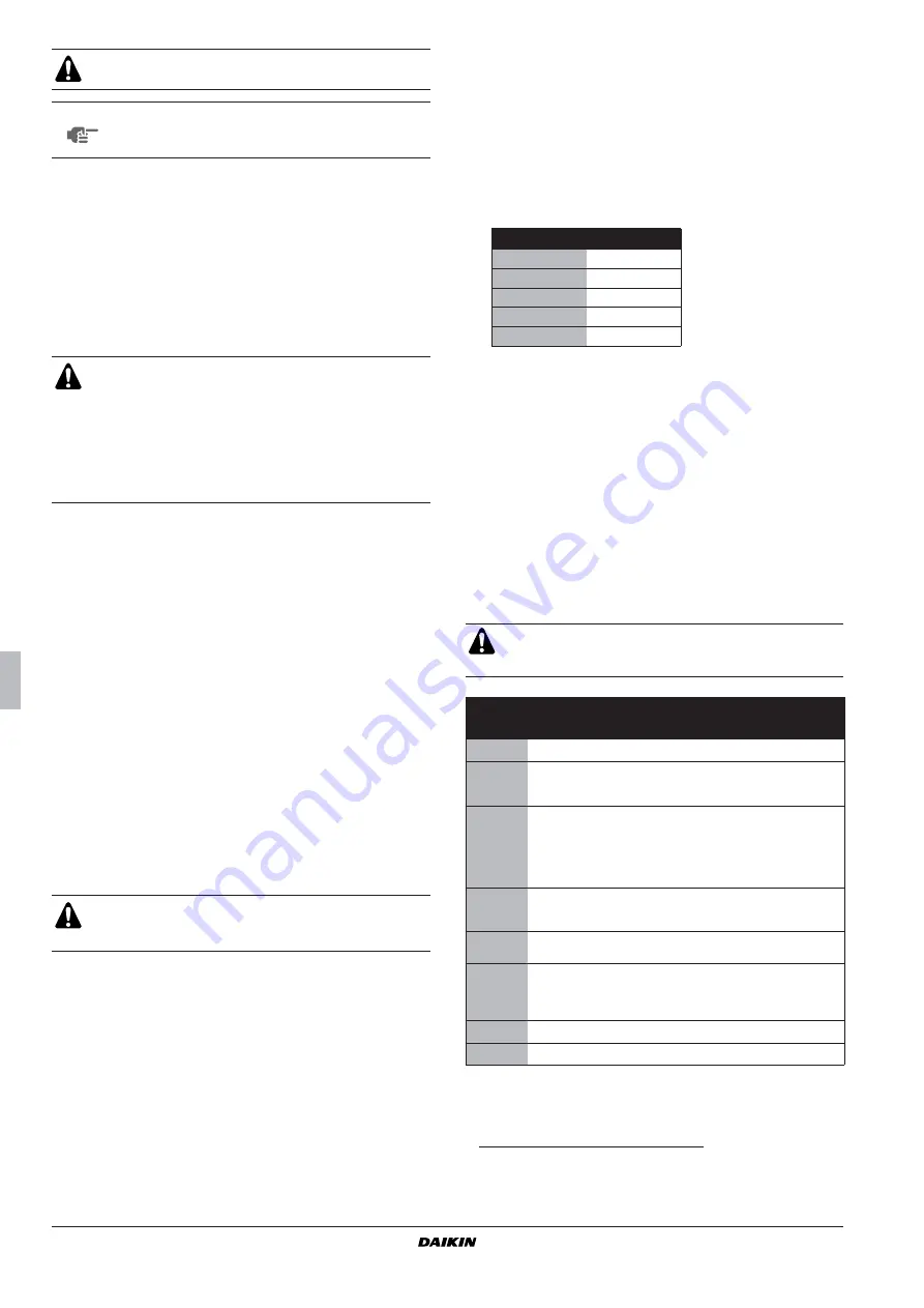
This equipment complies with EN/IEC 61000-3-11

(1)

  provided

that the system impedance Z

sys

 is less than or equal to Z

max

 at

the interface point between the user's supply and the public
system. It is the responsibility of the installer or user of the
equipment to ensure, by consultation with the distribution
network operator if necessary, that the equipment is connected
only to a supply with a system impedance Z

sys

  less than or

equal to Z

max

.

Only for EWWQ014~064: Equipment complying with 

EN/IEC 61000-3-12

(2)

Interconnection cables

Voltage free contacts
The PCB is provided with some voltage free contacts to indicate
the status of the unit. These voltage free contacts can be wired
as described on the wiring diagram.

Remote inputs
Besides the voltage free contacts, there are also possibilities to
install remote inputs.
They can be installed as shown on the wiring diagram.

B

EFORE


STARTING


The water pressure should not exceed the maximum
working pressure of 10 bar.

NOTE

Provide adequate safeguards in the water circuit to
make sure that the water pressure will never exceed
the maximum allowable working pressure.

All field wiring and components must be installed by a
licensed electrician and must comply with relevant Euro-
pean and national regulations.

The field wiring must be carried out in accordance with the
wiring diagram supplied with the unit and the instructions
given below.

Be sure to use a dedicated power circuit. Never use a
power supply shared by another appliance.

Switch off the main isolator switch before making any
connections (switch off the circuit breaker, remove or
switch off the fuses).

(1) European/International Technical Standard setting the limits for voltage 

changes, voltage fluctuations and flicker in public low-voltage supply 
systems for equipment with rated current 

75 A.

Z

max

 (

)

EWWQ014

0.28

EWWQ025

0.23

EWWQ033

0.21

EWWQ049

0.22

EWWQ064

0.20

(2) European/International Technical Standard setting the limits for harmonic 

currents produced by equipment connected to public low-voltage systems 
with input current >16 A and 

75 A per phase.

The unit should not be started, not even for a very short
period of time, before the following pre-commissioning
checklist is filled out completely.

tick 


when 

checked

standard steps to go through before starting the unit

1

Check for external damage.

2

Install main fuses, earth leak detector and main switch.
Recommended fuses: aM according to IEC standard 269-2.
Refer to the wiring diagram for size.

3

Supply the main voltage and check if it is within the allowable 
±10% limits of the nameplate rating.
The electrical main power supply must be arranged so, that it 
can be switched on or off independently of the electrical supply 
to other items of the plant and equipment in general.
Refer to the wiring diagram, terminals N, L1, L2 and L3.

4

Supply water to the evaporator and verify if waterflow is within 
the limits as given in the table under "Water charge, flow and 
quality" on page 3.

5

The piping must be completely purged. See also chapter 
"Checking the water circuit" on page 2.

6

Connect the flowswitch and pumpcontact, so that the unit 
can only come in operation when the waterpumps are running 
and the waterflow is sufficient. Make sure a water filter is 
installed before the water inlet of the unit.

7

Connect the optional field wiring for pumps start-stop.

8

Connect the optional field wiring for remote control.

Содержание HYDROCUBE EWWQ014KBW1N

Страница 1: ...par eau Fran ais Montagehandleiding Watergekoelde ijswaterkoelgroepen Nederlands Manual de instalaci n Enfriadores de agua empaquetados Espa ol Manuale d installazione Refrigeratori d acqua monoblocco...

Страница 2: ......

Страница 3: ...al specifications 1 Electrical specifications 1 Options and features 1 Options Glycol application for chilled water temperature down to 10 C or 5 C BMS connection MODBUS optional kit address card EKAC...

Страница 4: ...the pallet 3 Remove the four screws xing the unit to the pallet 4 Level the unit in both directions 5 Use four anchor bolts with M8 thread to x the unit in concrete directly or using the oor standing...

Страница 5: ...CHARGE FLOW AND QUALITY To assure proper operation of the unit a minimum water volume is required in the system and the water ow through the evaporator must be within the operation range as speci ed i...

Страница 6: ...be installed as shown on the wiring diagram BEFORE STARTING The water pressure should not exceed the maximum working pressure of 10 bar NOTE Provide adequate safeguards in the water circuit to make su...

Страница 7: ...operation instructions form and x it visibly near the operating site of the refrigeration system NOTES NOTE Try to reduce the drilling in the unit to a minimum If drilling is impreventable remove the...

Страница 8: ...Installation manual 6 EWWQ014 064KBW1N Packaged water cooled water chillers D EIMHP00908 17EU NOTES...

Страница 9: ...rcuit The operation of the water chiller is then controlled by the Digital Display Controller Shut down by switching off the controller and the circuit breaker of the power circuit EWWQ WARNINGS Emerg...

Страница 10: ...he Daten 1 Technische Daten zur Elektrik 1 Optionen und Funktionen 1 Optionen Glykolanwendung f r eine Temperatur des gek hlten Wassers bis 10 C oder 5 C MODBUS f r BMS Verbindung Adresskarte EKAC10C...

Страница 11: ...er Schrauben mit denen die Einheit auf der Palette befestigt ist 4 Richten Sie die Einheit in beiden Richtungen korrekt aus 5 Zur Befestigung der Einheit auf einem Zementsockel oder boden direkt oder...

Страница 12: ...en Sie daher bitte alles Folgende wenn Sie den Wasserkreislauf anschlie en 1 Verwenden Sie nur saubere Rohre 2 Halten Sie beim Entgraten das Rohrende nach unten 3 Decken Sie das Rohrende ab wenn Sie e...

Страница 13: ...danz Zsys kleiner oder gleich Zmax Es liegt in der Verantwortung des Installateurs oder des Anlagen Benutzers gegebenenfalls nach Konsultation des Netzbetreibers Folgendes sicherzustellen Die Anlage w...

Страница 14: ...andere Teile der Anlage oder das gesamte System ein oder ausgeschaltet werden kann siehe Elektroschaltplan f r Klemmen N L1 L2 und L3 4 Speisen Sie den Verdampfer mit Wasser und berpr fen Sie ob der W...

Страница 15: ...Betrieb des Kaltwassererzeugers wird danach vom Digitalanzeigenregler gesteuert Schalten Sie den Regler und den Leistungsschalter aus WARNHINWEISE Abschalten im Notfall Schalten Sie den Schutzschalter...

Страница 16: ...iveau de pression sonore est inf rieur 70 dB A Sp cifications techniques 1 Sp cifications lectriques 1 Options et fonctions 1 Options Application au glycol pour une temp rature d eau refroidie de 10 C...

Страница 17: ...able 4 S lectionner l emplacement de l appareil de telle fa on que le bruit occasionn ne d range personne 5 S assurer que l eau ne peut pas provoquer de dommage cet emplacement en cas de fuite de l un...

Страница 18: ...t me 3 Des purgeurs d air doivent tre pr vus tous les points sup rieurs du syst me Ils doivent tre situ s des endroits facilement accessibles pour l entretien 4 Le ltre eau install en face des pompes...

Страница 19: ...alimentation du groupe d eau glac refroidi par eau 1 A l aide du c ble appropri brancher le circuit lectrique aux bornes N L1 L2 et L3 de l unit section de c ble 2 5 10 mm2 2 Raccorder le conducteur d...

Страница 20: ...iner le format 3 Alimenter la tension principale puis v ri er si elle se situe dans les limites admissibles de 10 de la puissance nominale L alimentation lectrique principale doit tre con ue de telle...

Страница 21: ...ue Le fonctionnement du groupe d eau glac e est alors surveill par le contr leur af chage num rique Mettez l apparail l arr t en coupant le contr leur et le disjoncteur du circuit lectrique AVERTISSEM...

Страница 22: ...che specificaties 1 Opties en eigenschappen 1 Opties Toepassing van glycol voor verlaging van koelwatertemperatuur tot 10 C of 5 C BMS aansluiting MODBUS optionele setadreskaart EKAC10C 2 Interface vo...

Страница 23: ...dingen van de pallet 3 Verwijder de vier schroeven waarmee de unit aan het palet is bevestigd 4 Zet de unit in beide richtingen waterpas 5 Bevestig de unit met vier M8 ankerbouten in beton rechtstreek...

Страница 24: ...n het watercircuit steeds rekening houden met het volgende 1 Gebruik uitsluitend zuivere leidingen 2 Houd de uiteinden van de leidingen omlaag tijdens het verwijderen van bramen 3 Dek de uiteinden van...

Страница 25: ...rantwoordelijkheid van de installateur of de gebruiker van de apparatuur om ervoor te zorgen indien nodig in overleg met de distributienetwerkbeheerder dat de apparatuur alleen wordt aangesloten op ee...

Страница 26: ...hakeld onafhankelijk van de elektrische voeding van het systeem en de uitrusting in het algemeen Raadpleeg het elektrisch schema klemmen N L1 L2 en L3 4 Zorg voor watertoevoer in de verdamper en contr...

Страница 27: ...ater koelgroep wordt dan bestuurd door het besturingssysteem met digitaal scherm DDC Stop de werking door het besturingssysteem en de werkschakelaar van het voedingscircuit uit te schakelen WAARSCHUWI...

Страница 28: ...o cuali cados en tiendas industria ligera o granjas o por personas no versadas para uso comercial El nivel de presi n sonora es inferior a 70 dB A Especificaciones t cnicas 1 Especificaciones el ctric...

Страница 29: ...ecuado para las reparaciones 3 Veri que que no haya peligro de incendio debido a p rdidas de gas in amable 4 Seleccione la ubicaci n de la unidad de manera que el sonido generado por la unidad no mole...

Страница 30: ...re en todos los puntos altos del sistema Las salidas de aire deben colocarse en puntos f cilmente accesibles para el mantenimiento 4 El ltro de agua debe instalarse delante de la unidad para eliminar...

Страница 31: ...te el circuito el ctrico a los terminales N L1 L2 y L3 de la unidad secci n del cable 2 5 10 mm2 2 Conecte el conductor de masa amarillo verde al terminal de masa PE Punto de atenci n en relaci n a la...

Страница 32: ...je principal y veri que si se encuentra dentro de los l mites autorizados de 10 de la placa de identi caci n La alimentaci n el ctrica de la unidad debe instalarse de tal forma que puede ponerse en po...

Страница 33: ...go el funciona miento de la enfriadora de agua se controla mediante el controlador de pantalla digital Se apaga desactivando el controlador y la protecci n termomagn tica del circuito el ctrico ADVERT...

Страница 34: ...uesto apparecchio destinato ad essere utilizzato da utenti esperti o quali cati nei negozi nell industria leggera e nelle fattorie o per uso commerciale da persone non esperte Il livello di pressione...

Страница 35: ...ve essere suf ciente per interventi tecnici 3 Non devono esserci pericoli d incendio derivanti da perdite di gas in ammabili 4 Scegliere una posizione in cui il rumore generato dall apparecchio non di...

Страница 36: ...i valvole di sfogo dell aria Le valvole devono essere installate in posizioni facilmente accessibili al personale di manutenzione 4 Il ltro dell acqua deve essere installato anteriormente all apparecc...

Страница 37: ...usibili da usare Collegamento dell alimentazione elettrica al refrigeratore raffreddato ad acqua 1 Collegare la rete ai morsetti N L1 L2 ed L3 sezione del cavo 2 5 10 mm2 2 Collegare il cavo di messa...

Страница 38: ...Controllo della tensione d alimentazione che deve essere compresa tra il 10 del valore nominale di targa L alimentazione elettrica principale deve essere predisposta in modo da potere essere inserita...

Страница 39: ...ne controllato dal regolatore con display a cristalli liquidi Per arrestare l apparecchio disattivare il Regolatore ed aprire il teleruttore del circuito d alimentazione ATTENZIONE Arresto d emergenza...

Страница 40: ...EWWQ 70 dB A 1 1 1 10 C 5 C BMS MODBUS EKAC10C 2 EKRUMCA EKAC10C 2 EWWQ014KBW1N EWWQ064KBW1N EWWQ025KBW1N EWWQ033KBW1N EWWQ049KBW1N DAIKIN DAIKIN 1 EWWQ 014 025 033 x xB mm 600x600x600 kg 120 170 175...

Страница 41: ...4 15 16 17 18 19 1 2 3 4 5 1 2 3 4 5 8 6 R410A GWP 1 2090 1 wGWP LWC LWE a b 0 10 20 10 5 5 32 0 10 20 30 40 50 60 LWC 55 45 ZL ZL ZH ZH ZL ZH 1 5 1 5 1 5 a b a b a b 0 10 20 10 5 5 32 0 10 20 30 40 5...

Страница 42: ...7 0 8 0 A B mS m 25 C 40 30 30 30 A B mg Cl l 50 50 50 50 A mg SO4 2 l 50 50 50 50 A pH 4 8 mg CaCO3 l 50 50 50 50 B mg CaCO3 l 70 70 70 70 B mg CaCO3 l 50 50 50 50 B mg SiO2 l 30 30 30 30 B mg Fe l...

Страница 43: ...outlook 1 2 3 F1 2 3 H3P H4P H5P 1 2 PE S7S S9S 1 2 1 L1 L2 L3 2 5 10 2 2 l EWWQ014 62 31 l min 75 l min EWWQ025 134 53 l min 123 l min EWWQ033 155 76 l min 186 l min EWWQ049 205 101 l min 247 l min E...

Страница 44: ...IMHP00908 17EU EN IEC 61000 3 11 1 Zsys Zmax Zsys Zmax EWWQ014 064 EN IEC 61000 3 12 2 1 75 A Zmax EWWQ014 0 28 EWWQ025 0 23 EWWQ033 0 21 EWWQ049 0 22 EWWQ064 0 20 2 16 A 75 A 1 2 aM 269 2 IEC 3 10 N...

Страница 45: ...EWWQ KB DAIKIN EUROPE V Hz A 41 7 bar kg R410A R410A...

Страница 46: ...pequenas ind strias e explora es agr colas ou para utiliza o comercial por pessoas sem forma o espec ca O n vel de press o sonora inferior a 70 dB A Especifica es t cnicas 1 Especifica es el ctricas...

Страница 47: ...de que a gua n o causa danos no local em caso de fuga da mesma do aparelho O equipamento n o se destina a ser utilizado em ambientes potencialmente explosivos INSPEC O E MANUSEAMENTO DA UNIDADE Aquan...

Страница 48: ...A A corros o B incrusta es LIGA O DO CIRCUITO DA GUA O evaporador e o condensador est o equipados com uma rosca macho de tubo de g s para a entrada e sa da de gua consulte o diagrama geral As liga es...

Страница 49: ...de de distribui o de que o equipamento s ligado a uma fonte de alimenta o com imped ncia do sistema Zsys igual ou inferior ao valor Zmax Apenas para EWWQ014 064 Equipamento em conformidade com a norma...

Страница 50: ...osta de modo a poder ser ligada e desligada independentemente da alimenta o el ctrica de outros elementos da instala o e equipamento em geral Consulte o diagrama de liga es terminais N L1 L2 e L3 4 Ab...

Страница 51: ...A opera o do sistema de ar condicionado ent o controlada por controlador de Visor Digital Parar desligando o controlador e o disjuntor do circuito de alimenta o AVISOS Paragem de emerg ncia Desligar o...

Страница 52: ...kin EWWQ 70 1 1 1 10 C 5 C BMS MODBUS EKAC10C 2 EKRUMCA EKAC10C 2 EWWQ014KBW1N EWWQ064KBW1N EWWQ025KBW1N EWWQ033KBW1N EWWQ049KBW1N DAIKIN DAIKIN 1 Engineering Data Book EWWQ 014 025 033 600x600x600 12...

Страница 53: ...13 14 15 16 17 18 19 1 2 3 4 5 1 2 3 4 5 M8 6 R410A 1 2090 1 LWC LWE a b 0 10 20 10 5 5 32 0 10 20 30 40 50 60 LWC 55 45 ZL ZL ZH ZH ZL ZH 1 5 1 5 1 5 a b a b a b 0 10 20 10 5 5 32 0 10 20 30 40 50 60...

Страница 54: ...pH 25 C 6 8 8 0 6 8 8 0 7 0 8 0 7 0 8 0 A B 25 C 40 30 30 30 A B Cl 50 50 50 50 A SO4 2 50 50 50 50 A pH 4 8 CaCO3 50 50 50 50 B CaCO3 70 70 70 70 B CaCO3 50 50 50 50 B SiO2 30 30 30 30 B Fe 1 0 0 3...

Страница 55: ...Q014 064KBW1N D EIMHP00908 17EU 4 1 2 3 F1 2 3 H3P H4P H5P 1 2 PE S7S S9S 1 2 1 N L1 L2 L3 2 5 10 2 2 PE EWWQ014 62 31 75 EWWQ025 134 53 123 EWWQ033 155 76 186 EWWQ049 205 101 247 EWWQ064 311 152 373...

Страница 56: ...MHP00908 17EU EN IEC 61000 3 11 1 Zsys Zmax Zsys Zmax T EWWQ014 064 EN IEC 61000 3 12 2 1 75 A Zmax EWWQ014 0 28 EWWQ025 0 23 EWWQ033 0 21 EWWQ049 0 22 EWWQ064 0 20 2 16 A 75 A 1 2 aM IEC 269 2 3 10 N...

Страница 57: ...EWWQ KB DAIKIN 41 7 R410A R410A...

Страница 58: ...NOTES...

Страница 59: ...NOTES...

Страница 60: ...D EIMHP00908 17EU...

Отзывы: