Daikin EWAQ080DAYN Скачать руководство пользователя страница 23

EWAQ080~260DAYN
Packaged air-cooled water chillers
4PW35556-1E

Operation manual

22

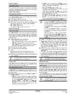
Symptom 6: Unit stops soon after operation

6

Symptom 7: Sensor error

 0C9

/

0CA

/

0H9:*** SENSOR ERR

7

Symptom 8: The alarm message shows


0U3:REMOCON SW ERR

8

Symptom 9: The alarm message shows


0U4:EXT PCB COMM.ERR

9

Symptom 10: The alarm message shows


0U4:MAINPCB COMM.ERR

10

Symptom 11: The alarm message shows


0U5:PCB COMM.PROBLEM

11

Symptom 12: The


NETWORK SAFETY 

alarm message shows


0U4:PCB COMM.PROBLEM

12

Symptom 13: The 

NETWORK SAFETY 

alarm message shows


0U4:SW VERSION ERR

13

Symptom 14: The water pressure can not be maintained

M

AINTENANCE

In order to ensure optimal availability of the unit, a number of checks
and inspections on the unit and the field wiring have to be carried out
at regular intervals.

If the unit is used for air conditioning application, the described
checks must be executed at least once a year. In case the unit is
used for other applications, the checks must be executed every
4 months.

Maintenance activities

Air heat exchanger
Remove dust and any other contaminant from the coil fins using
a brush and a blower. Blow from the inside of the unit. Take care
not to bend or damage the fins.

Field wiring and power supply

Check the power supply voltage on the local supply panel. The
voltage must correspond to the voltage marked on the identifi-
cation label of the unit.

Check the connections and make sure they are properly fixed.

Check the proper operation of the circuit breaker and the earth
leak detector provided on the local supply panel.

Internal wiring of the unit
Visually check the switch boxes on loose connections (terminals
and components). Make sure that the electrical components are
not damaged or loose.

Earth connection
Make sure that the earth wires are still connected properly and
that the earth terminals are tightened.

Refrigerant circuit

Check for leaks inside the unit. In case a leak is detected, call
your local dealer.

Check the working pressure of the unit. Refer to 

"Switching the

unit on" on page 8

.

Compressor

Check on oil leaks. If there is an oil leak, call your local dealer.

Check for abnormal noises and vibrations. If the compressor is
damaged, call your local dealer.

Fan motor

Clean the cooling ribs of the motor.

Check on abnormal noises. If the fan or motor are damaged, call
your local dealer.

P

OSSIBLE


CAUSES

C

ORRECTIVE


ACTION

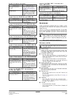
One of the safety devices is 
activated. 

Check safety devices (refer to 

Symptom 5: Safety devices are 
activated and alarm messages are 
displayed

).

Voltage is too low.

Test the voltage in the supply panel 
and, if necessary, in the electrical 
compartment of the unit (voltage 
drop due to supply cables is too 
high).

P

OSSIBLE


CAUSES

C

ORRECTIVE


ACTION

The sensor is broken or not correctly 
wired.

Check if the wiring is according to 
the wiring diagram.
Call your local dealer.

P

OSSIBLE


CAUSES

C

ORRECTIVE


ACTION

The software for the wired remote 
controller (A4P or A5P) is corrupt or 
absent.

Check if the wiring to the main PCB 
(A11P) is according to the wiring 
diagram.
Check if the "address setting" and 
the "terminator resistor setting" by 
DIP-switch is according to the setting 
mentioned in the wiring diagram.
Call your local dealer.

P

OSSIBLE


CAUSES

C

ORRECTIVE


ACTION

The extension PCB (A01P) can not 
be found.

Check if the wiring to the extension 
PCB (A01P) is according to the 
wiring diagram.
Call your local dealer.

P

OSSIBLE


CAUSES

C

ORRECTIVE


ACTION

The main PCB of circuit 2 (A21P) 
can not be found.

Check if the wiring to the main PCB 
of circuit 2 (A21P) is according to the 
wiring diagram.
Check if the "address setting" and 
the "terminator resistor setting" by 
DIP-switch is according to the setting 
mentioned in the wiring diagram.
Call your local dealer.

P

OSSIBLE


CAUSES

C

ORRECTIVE


ACTION

The wired remote controller (A4P or 
A5P (EKRUPG)) has no correct 
communication with the main PCB 
(A11P).

Check if the wiring to the main PCB 
(A11P) is according to the wiring 
diagram.
Check if the "address setting" and 
the "terminator resistor setting" by 
DIP-switch is according to the setting 
mentioned in the wiring diagram.
Call your local dealer.

P

OSSIBLE


CAUSES

C

ORRECTIVE


ACTION

The unit can not be found by the 
DICN system (EKACPG)

Check if the wiring between units is 
according to the wiring diagram.

• Make sure all the units in the DICN system 

are powered up.

• Make sure that the correct number of slave 

units is defined in the master unit.

• Make sure that the correct unit address 

setting is defined in each unit (refer to the 
installation manual).

P

OSSIBLE


CAUSES

C

ORRECTIVE


ACTION

All units in the DICN system 
(EKACPG) do not have the same 
software version.

Check the software version of each 
unit.
Call your local dealer in case a 
software upgrade is necessary.

P

OSSIBLE


CAUSES

C

ORRECTIVE


ACTION

There is a leak in the water circuit.

Check for any leaks in the water 
circuit.

The expansion vessel is broken or 
does not work properly.

Replace the expansion vessel.

Before carrying out any maintenance or repair activity,
always switch off the circuit breaker on the supply panel,
remove the fuses or open the protection devices of the
unit.

Never clean the unit with water under pressure.

The wiring and power supply must be checked by a
licensed electrician.

Содержание EWAQ080DAYN

Страница 1: ...OPERATION MANUAL EWAQ080DAYN EWAQ100DAYN EWAQ130DAYN EWAQ150DAYN EWAQ180DAYN EWAQ210DAYN EWAQ240DAYN EWAQ260DAYN Packaged air cooled water chillers...

Страница 2: ...make sure that it has been properly installed It is therefore necessary to carefully read the installation manual supplied with the unit and the recommendations listed in Checks before initial start u...

Страница 3: ...15 15 20 20 13 13 13 13 15 15 15 15 Phase 3 Frequency Hz 50 Voltage V 400 Nominal running current Circuit 1 Circuit 2 A A 39 39 51 51 35 35 35 35 39 39 39 39 Control and fan motor Phase 1 Frequency Hz...

Страница 4: ...erature sensor R1T 29 Pump optional 2 Condenser 15 Drier charge valve 30 Buffertank optional 3 Compressor 16 Power supply intake 31 Expansion vessel optional 4 Electronic expansion valve sight glass w...

Страница 5: ...ansion valve The expansion valve brings the liquid refrigerant to a pressure at which it can easily be evaporated in the evaporator p p p M12C M11C p p p M22C M21C M15F M13F M14F M25F M23F M24F B1PH B...

Страница 6: ...and reliable protection against overheating overloading phase loss and phase reversal The controller will detect the shut down of the compressor The controller needs to be reset manually Reverse phas...

Страница 7: ...S Fan overcurrent relay for circuit 1 K15F Fancontactor for circuit 1 only for EWAQ080 100 and EWAQ180 260 K15S Fan overcurrent relay for circuit 1 only for EWAQ080 100 and EWAQ180 260 K16F Fancontact...

Страница 8: ...her material 11 Power supply voltage Check the power supply voltage on the local supply panel The voltage should correspond to the voltage on the identification label of the unit 12 Water connection C...

Страница 9: ...l operational information on page 9 Adjusting the temperature setpoint on page 10 Resetting the unit on page 10 Setting the language If desired the operating language can be changed to any of the foll...

Страница 10: ...ond number stands for the dew point saturation temperature in degrees Celsius LOWNOISE at the bottom of the first screen the status of the lownoise setting is shown Y active or N not active 6 Press th...

Страница 11: ...network safeties When a unit or circuit safety occurs the compressor is shut down The safeties menu will indicate which safety is activated The UNIT STATUS screen of the readout menu will indicate OF...

Страница 12: ...1 and the capacity of the unit To consult information about the unit status of circuit 2 only for EWAQ130 260 To consult actual operational informa tion about the current Ampere and voltage of the un...

Страница 13: ...in BUZZER IF SAFETY YES _ ADVANCED BACKLIGHT TIME 05min GRAPHIC READOUT YES ENTER SERVICE PASSWORD 0000 TO LOGIN To check the actual value of the general software timer To check the actual value of th...

Страница 14: ...T HISTORY 002 C21RH 00000hCS 00000 _ UNIT HISTORY 002 C22RH 00000hCS 00000 _ UNIT HISTORY 002 AI1 NONE AI2 NONE _ UNIT HISTORY 002 AI3 NONE AI4 NONE To consult time and date information To consult add...

Страница 15: ...nex I on page 25 Defining and activating the control mode The unit is equipped with a thermostat which controls the cooling capacity of the unit Select the appropriate mode MANUAL CONTROL manual contr...

Страница 16: ...ntrol The DUAL PUMP screen of the usersettings menu allows the user to define the steering of two pumps for this to be possible a changeable digital output has to be configured for a second pump in th...

Страница 17: ...however will only come into operation if another unit is in alarm another unit is in DISCONNECT ON OFF mode the setpoint is not reached when all other units have been running on full capacity for some...

Страница 18: ...TIME M RT 120 sec starts counting when the compressor has started During the count down the compressor will not be switched off by the thermostat function To check the actual value of the software tim...

Страница 19: ...witch setpoint 1 or setpoint 2 REMOTE ON OFF indicates the position of the remote on off switch CAP LIMIT 25 50 75 SET indicates the position of the enable disable capacity limitation switches LOW NOI...

Страница 20: ...to enter and select the next number When pressing the key on the last number the confirmation of the new password is completed TROUBLESHOOTING This section provides useful information for diagnosing a...

Страница 21: ...vated and alarm messages are displayed The ON LED is broken Contact your local dealer Message safety menu Symptom POSSIBLE CAUSES CORRECTIVE ACTION One of the following safety devices is activated Com...

Страница 22: ...or is not locked RESET After temperature decrease the thermal protector is reset automatically and the compressor will start again This is not detected by the controller If the protector is activated...

Страница 23: ...ges are displayed Voltage is too low Test the voltage in the supply panel and if necessary in the electrical compartment of the unit voltage drop due to supply cables is too high POSSIBLE CAUSES CORRE...

Страница 24: ...damage and make sure that the hole diameter size all over the filter surface is still 1 0 mm maximum Water sensors Check that all the water sensors are correctly fixed into the inlet and outlet water...

Страница 25: ...EWAQ080 260DAYN Packaged air cooled water chillers 4PW35556 1E Operation manual 24 NOTES...

Страница 26: ...e DICN setup Example A DICN setup with 2 units means load up requests of maximum 2 compressors at a time INLET CONTROL Default value Lower limit Upper limit Units 1 circuit Units 2 circuits Step diffe...

Страница 27: ...TING SETPOINT MODE AMBIENT MAXPOS 03 0 NEG 00 0 RF 020 0 SLOPE 006 0 12 0 C 13 5 C 15 0 C 18 0 C 17 5 C 10 0 C 20 0 C 6 0 C 3 0 C 10 0 C A B AMBIENT _ FLOATING SETPOINT MODE CH AI SLOPE NTC MAXPOS 03...

Страница 28: ...0 INLET WATER 013 6 OUTLET WATER 007 0 _v UNIT HISTORY 001 1E6 COMPR 1 SAFETY 22h33m00s 23 03 06 COOL INLSP1 012 0 _ UNIT INFO FAN ST VA Y 2PUMP Y HEATERTAPE Y FAN DO ST 2 DO INV 2 ENTER PASSWORD PAS...

Страница 29: ...NE OPEN DO5 NONE OPEN _ UNIT STATUS C11 OFF SAFETY ACT C12 OFF SAFETY ACT UNIT CAPACITY 000 _ UNIT STATUS C21 OFF SAFETY ACT C22 OFF SAFETY ACT _ C1 ACT PRESSURES HP1 019 0b 050 8 LP1 004 4b 05 2 FAN1...

Страница 30: ...4PW35556 1E Copyright Daikin...

Отзывы: