


EWAQ080~260DAYN
Packaged air-cooled water chillers
4PW35556-1E
Operation manual
16
Submenu: Language
Defining the language
This screen allows the user to define the language of the displayed
information of the controller (on the first screen). (Push the
‡
button
repeatedly to change the operating language).
Submenu: Time and date
Defining the time and date
The
TIME AND DATE
screen of the usersettings menu allows the
user to define the time and date.
■
TIME
: used to define the present time.
■
DATE FORMAT
: used to define the format of the date.
■
DATE
: select the name of the present day and define the
present date according to the setting of the
DATE FORMAT
.
DD
= number of day (01~31),
MM
= number of month (01~12)
YY
= the last 2 numbers of the year (2006 = 06).
Submenu: Free cooling
Defining free cooling
The
FREE COOLING
screen of the usersettings menu allows the
user to control a 3-way water valve when the unit is in free cooling
state. To make this possible a changeable digital input or output has
to be configured for free cooling in the service menu. (Refer to the
installation manual.)
■
MODE
: used to define the free cooling mode.
•
NOT ACTIVE
: free cooling is not active.
•
CHDI
: changeable digital input will activate the free cooling mode
•
AMBIENT
: free cooling is based on ambient temperature.
•
INLET-AMBIENT
: free cooling is based on the difference
between inlet water temperature and ambient temperature.
■
SP
: setting of the free cooling setpoint.
■
DIF
: setting of the free cooling difference.
■
PUMP
■
ON
: pump will be on when free cooling mode is active
■
OFF
: pump will be off when free cooling mode is active
■
LEAD
: time that the pump will be running before the compressor
will start operating.
Submenu: DICN
Only available in case DICN (option kit EKACPG) is installed (refer to
"Connection and setup of a DICN system" in the installation manual
and the installation manual of the EKACPG kit).
Defining the network settings
The
SETTINGS
screen of the network menu allows the user to set
the
MODE
of the unit, the
OFFSET
time and the condition when the
pump must operate.
■
MODE
: Define the mode of the unit as
NORMAL
,
STANDBY
or
DISCONN ON/OFF
.
•
NORMAL
: The unit is controlled by the network. Loading and
unloading is decided by the central control of the netwerk. Putting
this unit ON or OFF will also put all other units ON or OFF, unless
their status is
DISCONNECT ON/OFF
. (see further)
Changing
CONTROL SETTINGS
or
THERMOSTAT
SETTINGS
to this unit, will apply to all other units.
MANUAL
CONTROL
on such a unit is not possible. Refer to
"Defining and
activating the control mode" on page 14
.
•
STANDBY
: The unit is considered as a
NORMAL
unit and its
function is then also similar to a unit defined as
NORMAL
, but this
unit however, will only come into operation if:
another unit is in alarm
another unit is in
DISCONNECT ON/OFF
mode
the setpoint is not reached when all other units have been
running on full capacity for some time
If more than one unit is defined as
STANDBY
, only 1 of the units
will be really standby. The unit which is really standby will be
decided by the number of running hours.
•
DISCONNECT ON/OFF
: Putting this unit ON or OFF will not put
other units ON or OFF.
MANUAL CONTROL
on such a unit is
possible.
If the unit is put to
INLET
or
OUTLET
mode, and the unit is ON,
it will be controlled by the DICN network as a
NORMAL
unit.
■
OFFSET
: The
OFFSET
time defines the target difference in
running hours between one unit and another unit with
OFFSET:0000h
. This value is important for maintenance
purposes. The difference in setting among different units should
be high enough as to avoid servicing of the units all at the same
time. The lower and upper limits are
0
and
9000
hours
respectively. The default value is
0
hours.
■
PUMP ON IF
: Set if the pump must operate as long as the
chiller is on (
UNIT ON
), or during compressor on condition only
(
COMPR ON
).
When
UNIT ON
is selected, the pump output will remain closed
as long as the chiller is on. When
COMPR ON
is selected, the
pump output will remain closed as long as the compressor is on.
Also refer to the separate manual "Installation examples for a
DICN configuration".
Submenu: Advanced
Activating or deactivating the setpoints password and the unit
on/off password
The first
ADVANCED
screen of the usersettings menu allows the user
to activate or deactivate the user password needed to change the
temperature setpoint (
SETPOINT MENU
). When deactivated, the
user does not have to enter the password each time he wants to
change the setpoint.
The first
ADVANCED
screen of the usersettings menu also allows the
user to activate or deactivate the user password needed to switch the
unit ON or OFF (
UNIT ON/OFF
).
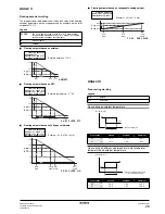
NOTE
A functional diagram showing the free cooling working
can be found in
"Annex III" on page 26
.
NOTE
Put a unit to
DISCONNECT ON/OFF
when servicing
the machine. In this case it is possible to switch ON or
OFF this unit without switching ON or OFF the other
units of the network.
It is also possible then to operate the unit in
MANUAL
CONTROL
.
Put a unit to
DISCONNECT ON/OFF
continuously if
the operator wants to decide by himself when this unit
must operate.
Note that in this case, it makes no sense to define
another unit of the network as
STANDBY
. Since there is
a unit set continuously to
DISCONNECT ON/OFF
, the
STANDBY
unit will continuously be considered as a
NORMAL
unit.
NOTE
The settings on this screen of the network menu must
be executed for all chillers connected to the system.
NOTE
If changed on one of the units in a DICN configuration,
this setting is automatically transferred to all the other
units in the network.