


EWAQ080~260DAYN
Packaged air-cooled water chillers
4PW35556-1E
Operation manual
14
User password menu
Æ
Network menu
∆
The "network" menu (only available in case DICN is installed)
provides useful information regarding the network.
Cool/heat menu
Í
This menu is not available for EWAQ units.
Tasks of the usersettings menu
Entering the usersettings menu
The usersettings menu is protected by the user password, a 4-digit
number between
0000
and
9999
.
1
Enter the
Å
USERSETTINGS MENU
. (Refer to the chapter
"How to enter a menu" on page 8
).
The controller will request the password.
2
Enter the correct password using the
fi
and
Ì
keys and press
‡
for each digit.
3
Press
‡
on the last digit to confirm the password and to enter
the usersettings menu.
The controller automatically shows the submenu screen.
To define settings of a certain function:
1
Go to the appropriate submenu of the usersettings menu using
the
fi
and
Ì
keys.
2
Press the
‡
key to enter the submenu of your choice.
3
Go to the appropriate screen using the
fi
and
Ì
keys. If there
is only one screen, the
fi
and
Ì
keys have no effect.
4
Press the
‡
key to move the cursor to the first parameter which
can now be modified.
5
Select the appropriate setting using the
fi
and
Ì
keys.
6
Press
‡
to confirm the selection.
When the selection has been confirmed, the cursor switches to
the next parameter which can now be modified.
7
Repeat instruction 6 to modify the other parameters.
8
After the last parameter the cursor is switched back to the
starting position and continue from instruction 3 onwards.
9
Press the
ƒ
key to return to the usersettings menu and
continue from instruction 1 onwards.
Submenu: Thermostat
Defining the thermostat settings
When inlet or outlet control mode is selected, the unit uses a
thermostat function to control the cooling capacity. However, the
thermostat parameters are not fixed and can be modified.
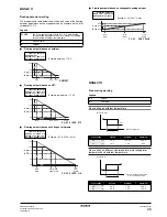
The default, limit and step values for the thermostat parameters are
shown in
"Annex I" on page 25
.
Defining and activating the control mode
The unit is equipped with a thermostat which controls the cooling
capacity of the unit. Select the appropriate mode:
■
MANUAL CONTROL
:manual control mode: the operator controls
the capacity himself by setting:
•
C11
/
12
/
21
/
22
(capacity step in manual mode): OFF or ON of
compressors 11/12/21/22.
•
F1*
,
F2*
(air flow in manual mode): off, low, medium or high of
circuit 1/2.
■
INL WATER
: inlet control mode: uses the entering water
temperature to control the capacity of the unit.
■
OUTL WATER
: outlet control mode: uses the leaving water
temperature to control the capacity of the unit.
To check the status of the changeable
digital inputs and outputs (second
screen).
To check the status of the changeable
digital outputs (third screen).
To check the status of the changeable
digital outputs and analogue inputs
(fourth screen).
To check the status of the changeable
analogue inputs and outputs (fifth
screen)
To overview which communication lines
are active.
To change the user password.
To define the user login and logout
status.
To change the login/logout password.
To consult the temperature setpoint, the
common entering water temperature
(entering water temperature of the
master unit).
The status screen of the network menu
shows the condition of the master unit
(
M
) and slave units (
SL1
...
SL3
).
_÷CHANG. DIG. INPUTS
DI4 NONE
DO1 W.(NO) :O
DO2 GEN.OPERATION :O
_÷CHANG. INP/OUTPUTS
DO3 NONE (OPEN)
DO4 NONE (OPEN)
DO5 NONE (OPEN)
_÷CHANG. INP/OUTPUTS
DO6 NONE (OPEN)
AI1 NONE
AI2 NONE
_÷CHANG. INP/OUTPUTS
AI3 NONE
AI4 NONE
AO1 NONE
_^ COMMUNICATION
RS232 ONLINE:N
RS485 ONLINE:N
DIII ONLINE:N
ENTER PASSWORD
PASSWORD: 0000
TO LOGIN
_v LOGIN/LOGOUT MENU
LOGIN STATUS:USER
LOGOUT? NO
_^ LOGIN/LOGOUT MENU
CHANGE PASSWORD
NEW PASSWORD: 0000
CONFIRM: 0000
_v NETWORK
COOL. INLSP1:012$0¢
INLET WATER:013$6¢
OUTLET WATER:007$0¢
_^M:NORMAL CAP:000%
SL1:NORMAL CAP:000%
SL2:NORMAL CAP:000%
SL3:NORMAL CAP:000%
NOTE
■
If changed on one of the units in a DICN
configuration, this setting is transferred to all other
units in the network.
■
A functional diagram showing the thermostat
parameters can be found in
"Annex I" on page 25
.