


EWAP400~540MBYNN
Packaged air-cooled water chillers
4PW22678-1B
Installation manual
6
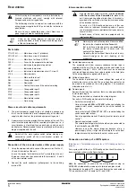
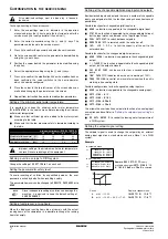
Setting the adresses on the digital controller
Set the addresses on the PCB by means of DIP-switches according
to the drawing below:
Where to find the DIP-switches of the digital controller
Important
Be sure to attach – in case of common leaving water control – the
optional temperature sensor.
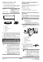
Cable for remote digital controller
See remote digital controller in the operation manual.
1
A remote digital controller can be connected to the PCB inside
the unit by means of a 6-ray cable and a connector located on
the rear side of the remote digital controller in case you prefer to
operate the unit from a distance. You are allowed to use a cable
of up to 600 metres. Specifications of the cable: 6-ray telephone
cable with a maximum cable resistance of 0.1
Ω
/m.
2
For units in a DICN configuration, the digital controllers of the
units can be installed remotely at a distance of up to 60 metres
by using a 6-ray telephone cable with a maximum cable
resistance of 0.1
Ω
/m.
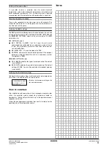
Setting the adresses on the remote digital controller
When a remote digital controller is used, the adress has to be set by
means of DIP-switches according to the drawing below:
Where to find the DIP-switches of the remote digital controller
B
EFORE
STARTING
I do confirm having executed and checked all the above
mentioned items.
Keep for future reference.
Master
Slave 1
Slave 2
Slave 3
PCB
address
Any unit can be master, slave 1, slave 2 or slave 3.
Master
Slave 1
Slave 2
Slave 3
Remote digital
controller address
Any unit can be master, slave 1, slave 2, slave 3...
To avoid damage to the controllers liquid crystals during
winter time, do not shut off the main power supply.
1 2 3 4 5 6
OFF
1 2 3 4 5 6
OFF
1 2 3 4 5 6
OFF
1 2 3 4 5 6
OFF
1 2 3 4 5 6
OFF
1 2 3 4 5 6
OFF
1 2 3 4 5 6
OFF
1 2 3 4 5 6
OFF
The unit should not be started, not even for a very short
period of time, before the following pre-commissioning
checklist is filled out completely.
tick
✓
when
checked
standard steps to go through before starting the unit
■
1
Check for external damage.
■
2
Open all shut-off valves indicated by a red label: "OPEN THIS
VALVE BEFORE OPERATION". (Open the liquid line, discharge
and suction (if provided) stop valves completely.)
■
3
Install main fuses, earth leak detector and main switch.
Recommended fuses: aM according to IEC standard 269-2.
Refer to the wiring diagram for size.
■
4
Supply the main voltage and check if it is within the allowable
±10% limits of the nameplate rating.
The electrical main power supply should be arranged so, that
it can be switched on or off independently of the electrical
supply to other items of the plant and equipment in general.
Refer to the wiring diagram, terminals L1, L2 and L3.
■
5
Supply water to the evaporator and verify if water flow is within
the limits as given in the table under
■
6
The piping must be completely purged.
■
7
Connect the pump contact in series with the contact of the
flowswitch, so that the unit can only come in operation when the
waterpumps are running and the water flow is sufficient.
For DICN configurations, every chiller shall have its own
flowswitch and shall be interlocked with the pump from which it
gets the flow.
■
8
Check the oil level in the compressors.
■
9
Connect the power supply to the heatertapes.
The heatertapes must be connected to an independent,
separately fused, power supply all year-round.
■
10
Install the filter kit supplied with the unit in front of the
evaporator water inlet. The filter has a mesh size of maximum
1.0 mm.
■
11
Check that all the water sensors are correctly fixed into the
heat exchanger (see also the sticker attached to the heat
exchanger).
NOTE
■
It is necessary to read the operation manual
delivered with the unit before operating the unit. It
will contribute to understand the operation of the
unit and its electronic controller.
■
Close all switch box doors after installation of the unit.
Date
Sign