


Installation manual
5
EWAP400~540MBYNN
Packaged air-cooled water chillers
4PW22678-1B
F
IELD
WIRING
Parts table
F11U-F13U ............Main fuses circuit 1 (standard)
F21U-F23U ............Main fuses circuit 2 (standard)
F1,2,3U ..................Main fuses for the unit (OP52)
F4,5U .....................Fuses for the evaporator heatertape
H1P ........................Indication lamp general operation
H2P ........................Indication lamp alarm
H3,4P .....................Indication lamp operation circuit 1, circuit 2
L1,2,3 .....................Main terminals
PE ..........................Main earth terminal
S6S ........................Changeable input 1
S8L.........................Flowswitch
S9L.........................Contact that closes if the pump is working
S10S ......................Changeable input 2
S11S ......................Changeable input 3
S12S ......................Changeable input 4
S13S ......................Main isolator switch
- - -..........................Field wiring
Power circuit and cable requirements
1
The electrical power supply to the unit should be arranged so
that it can be switched on or off independently of the electrical
supply to other items of the plant and equipment in general.
2
A power circuit must be provided for connection of the unit. This
circuit must be protected with the required safety devices, i.e. a
circuit breaker, a slow blow fuse on each phase and an earth
leak detector. Recommended fuses are mentioned on the wiring
diagram supplied with the unit.
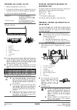
Connection of the air-cooled water chiller power supply
1
Using the appropriate cable, connect the power circuit to the L1,
L2 and L3 terminals of the unit.
In case the option "main isolator switch" is installed on the unit,
the power circuit must be connected to the terminals 2, 4 and 6
of the main isolator switch.
2
Connect the earth conductor (yellow/green) to the earthing
terminal PE.
Interconnection cables
■
Heater tape power supply
The evaporator and heat recovery condensor heater tape is
supplied with the unit. The heater tape must be connected to an
independent supply 1~50 Hz, 230 V and must be connected
year-round. Separate fuses have to be installed in the field (refer
to the wiring diagram supplied with the unit).
■
Voltage free contacts
The controller is provided with some voltage free contacts to
indicate the status of the unit. These voltage free contacts can
be wired as described on the wiring diagram. The maximum
allowable current is 4 A.
■
Remote inputs
Besides the voltage free contacts, there are also possibilities to
install remote inputs.
They can be installed as shown on the wiring diagram.
For units in DICN configuration, note the following:
•
Switch for remote on/off:
Units with status
or
will be controlled by the
remote on/off switch connected to the chiller defined as
.
Units with status
are controlled by the
switch connected to them.
See also operation manual: "Selecting local or remote on/off
control".
•
Remote dual setpoint switch:
The remote dual setpoint switch should only be connected to
the chiller defined as
.
However in case the master drops out because of e.g. a
power supply failure, it might be interesting to have the dual
temperature switch installed to the other units as well.
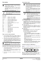
Connection and setup of a DICN system
(See
"Installation examples for a DICN configuration" on
)
For a system with chillers in a DICN configuration, the chillers have to
be connected as shown in the figure below.
Make the connection as shown on the wiring diagram using an
AWG20/22 shielded cable, made up of a twisted pair plus shield.
Pay attention to the polarity! TX+ on one chiller must be connected to
TX+ on another chiller. The same for TX– and GND.
All field wiring and components must be installed by a
licensed electrician and must comply with relevant
European and national regulations.
The field wiring must be carried out in accordance with the
wiring diagram supplied with the unit and the instructions
given below.
Be sure to use a dedicated power circuit. Never use a
power supply shared by another appliance.
NOTE
Verify on the wiring diagram all electrical actions
mentioned below, in order to understand the operation
of the unit more deeply.
Switch off the main isolator switch before making any
connections (switch off the circuit breaker, remove or
switch off the fuses).
A pump interlock contact must be installed in series
with the contact of the flowswitch to prevent the
unit from operating without water flow. A terminal is
provided in the switch box for the electrical connection
of the interlock contact.
For units in a DICN configuration, every chiller can
either have an individual circulation pump or 1 pump
can discharge water in a distributor that leads water to
several chillers.
In both cases, all units must be equipped with an
interlock contact!
NOTE
Normally the unit will not operate if there is no flow
thanks to the standard installed flowswitch.
But as to have a double safety, you must install
the pump interlock contact in series with the
contact of the flowswitch.
Operating the unit without flow will result in very
severe damage to the unit (freezing of the
evaporator).
1
2
3
4