


Installation manual
9
EWAP400~540MBYNN
Packaged air-cooled water chillers
4PW22678-1B
A
NNEX
I
Installation examples for a DICN configuration
I
NTRODUCTION
This annex introduces 3 installation examples to help you set up your
Daikin Integrated Chiller Network or DICN configuration.
Defining a unit in a setup of a DICN system
Change the setting of
to
on each unit.
E
XAMPLES
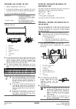
Field wiring and wiring parts table
........Field wiring
........Earth wiring
...........................Terminal on the unit
F1~F20...................Fuses
K1P~K4P................Pump contact (S9L on main wiring diagram)
L1,L2,L3,N..............Main supply terminals
M1P~M5P ..............Pump motor
R8T ........................Sensor for common leaving water in a DICN
system (EKCLWS)
R9T ........................Sensor for secondary circuit
S1S ........................Manual switch for pump of master unit
S6S (M,S3).............Remote start/stop switch
S10S ......................Dual setpoint selection switch
Y1S ........................3-way valve
Example 1: Single ring system with 1 pump
shows the system configuration, field wiring and terminals
for field wiring of this example.
Purpose
Purpose of this system is to deliver a constant water flow at a
constant temperature to a particular load. One unit, slave 3 (S3), is
kept as a standby unit.
Setup
■
The system is controlled on leaving water temperature. It is
required to install the additional sensor R8T (EKCLWS) in the
mixed water outlet and to connect it to the PCB of the master
unit.
■
The pump keeps running as long as 1 of the units is ON. After
switching OFF all units, the pump runs for a time indicated by
the
setting.
■
Slave 3 (S3) is configured to operate when its remote start/stop
switch S6S (S3) is pushed by the operator.
■
Slave 1 (S1), slave 2 (S2) and the master unit (M) are switched
ON or OFF using the remote start/stop switch S6S (M) which is
connected to the master unit.
■
The setpoint can be switched from
to
using the dual setpoint selection switch S10S
which is connected to the master unit.
Parameter settings of the units
Usersettings menu:
Changeable inputs/outputs must be defined as follows:
Service setting menu:
Remark
Slave 3 can be configured to start up automatically if:
■
1 of the other units is in alarm or;
■
all other units are running on full capacity and the setpoint is not
reached yet.
To have your slave 3 unit act this way, set its mode to
. In this
case, S6S (S3) has no function.
All field wiring and components must be installed by a
licensed electrician and must comply with relevant
European and national regulations.
The field wiring must be carried out in accordance with the
wiring diagram supplied with the unit and instructions given
below.
Be sure to use a dedicated power circuit. Never use a
power supply shared by another appliance.
All customized settings must be done by a licensed
technician.
NOTE
■
K*P can also be a 24 V DC or 230 V AC contactor.
■
The additional sensor R8T (EKCLWS) must be
connected directly to the PCB of the master unit.
Slave 3
Slave 2
Slave 1
Master
"
"
Slave 3
Slave 2
Slave 1
Master
Terminal 76-78
S10S DI1
Terminal 76-79
S6S DI2
Terminal 76-85
DI3
Terminal 76-86
DI4
Terminal 8T+8T–
R8T AI1