


General Outline
ESIE10-01
1–86
3
11
4
5
In case of sudden stop of the unit, follow the instructions on the Control Panel Operating Manual which
is part of the on-board documentation delivered to the end user with this manual. It is recommended
to perform installation and maintenance with other people. In case of accidental injury or unease, it is
necessary to:
Q
Keep calm.
Q
Press the alarm button if present in the installation site.
Q
Move the injured person in a warm place far from the unit and in rest position.
Q
Contact immediately emergency rescue personnel of the building or if the Health Emergency
Service.
Q
Wait without leaving the injured person alone until the rescue operators come.
Q
Give all necessary information to the rescue operators.
Warning:
Q
Before carrying out any operation on the machine, please read this instruction and operating
manual carefully. Installation and maintenance must be carried out by qualified personnel familiar
with the provisions of law and local regulations, and who has been properly trained or has
experience with this type of equipment.
Q
Avoid installing the machine in a place that could be dangerous during maintenance operations,
such as (but not only) platforms without parapets or railings, or areas not complying with the
clearance requirements.
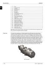
Moving and lifting
The machine must be moved and lifted by using cables, spacing bars and scales of appropriate
dimensions to the machine weight. This is stated on its identification plate. The table of weights
included in the manual should be considered as indicative only. Installation of certain accessories can
increase machine weight. Always refer to the dimensional diagrams supplied for any technical
information.
Block machine sliding on lorries to prevent damage to the panels and base frame. Avoid bumping,
jolting and impacts during unloading and/or moving the machine. Do not push or pull the machine from
any part other than the base frame. These falls could cause serious damages for which the
manufacturer will not be held liable.
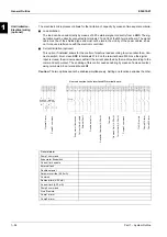
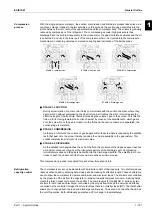
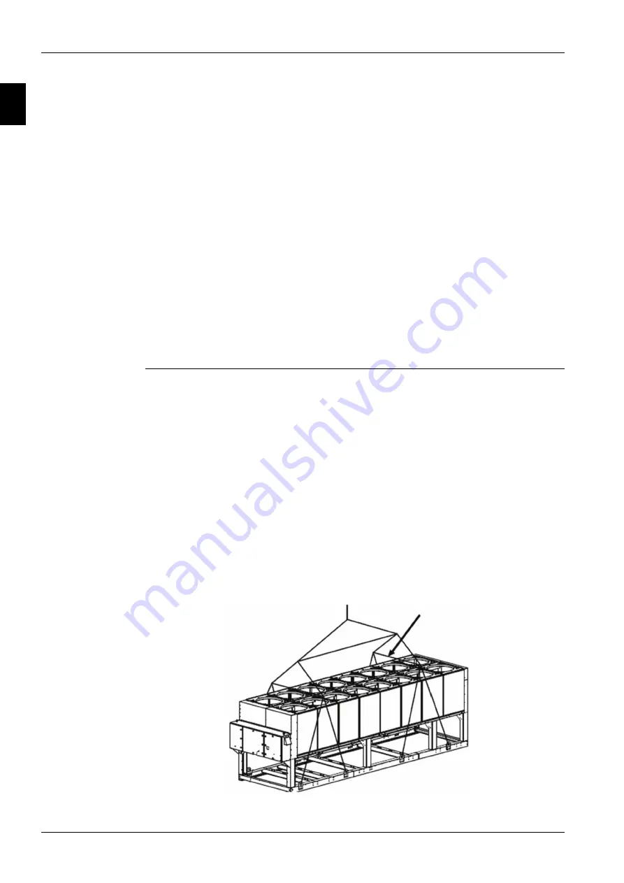
All units of the series are supplied with lifting points market in yellow. Only use these points to lift the
unit, as shown in the figure.
Use spacing bars to
prevent damage to the
condensation bank.
Position these above the
fan grills at a distance of
at least 2.5 metres.
Only use the designated lifting points marked on the unit.
Lifting the unit
L1
L2
L3
L4
N.B.:
The lifting method
specified below if valid for
all EWAD-C-models
Содержание EWAD620-C17C-SS
Страница 2: ......
Страница 8: ...ESIE10 01 1 2 Part 1 System Outline 3 1 1 5...
Страница 111: ...ESIE10 01 General Outline Part 1 System Outline 1 105 3 1 4 5 1 36 1 Power Compressor 1 2...
Страница 112: ...General Outline ESIE10 01 1 106 Part 1 System Outline 3 1 1 4 5 1 36 2 Power Compressor 3...
Страница 113: ...ESIE10 01 General Outline Part 1 System Outline 1 107 3 1 4 5 1 36 3 Kit Pumps...
Страница 114: ...General Outline ESIE10 01 1 108 Part 1 System Outline 3 1 1 4 5 1 36 4 Circuit Fan Power Supply 1...
Страница 115: ...ESIE10 01 General Outline Part 1 System Outline 1 109 3 1 4 5 1 36 5 Circuit Fan Power Supply 1...
Страница 116: ...General Outline ESIE10 01 1 110 Part 1 System Outline 3 1 1 4 5 1 36 6 Circuit Fan Power Supply 2...
Страница 117: ...ESIE10 01 General Outline Part 1 System Outline 1 111 3 1 4 5 1 36 7 Circuit Fan Power Supply 2...
Страница 118: ...General Outline ESIE10 01 1 112 Part 1 System Outline 3 1 1 4 5 1 36 8 Circuit Fan Power Supply 3...
Страница 119: ...ESIE10 01 General Outline Part 1 System Outline 1 113 3 1 4 5 1 36 9 Circuit Fan Power Supply 3...
Страница 120: ...General Outline ESIE10 01 1 114 Part 1 System Outline 3 1 1 4 5 1 36 10 Unit Control Circuit Power Supply...
Страница 121: ...ESIE10 01 General Outline Part 1 System Outline 1 115 3 1 4 5 1 36 11 Analog Inputs Output Board...
Страница 122: ...General Outline ESIE10 01 1 116 Part 1 System Outline 3 1 1 4 5 1 36 12 Digital Inputs Board...
Страница 123: ...ESIE10 01 General Outline Part 1 System Outline 1 117 3 1 4 5 1 36 13 Digital Outputs Board...
Страница 124: ...General Outline ESIE10 01 1 118 Part 1 System Outline 3 1 1 4 5 1 36 14 Digital Outputs Board...
Страница 125: ...ESIE10 01 General Outline Part 1 System Outline 1 119 3 1 4 5 1 36 15 Extension Control Fans 1 2...
Страница 126: ...General Outline ESIE10 01 1 120 Part 1 System Outline 3 1 1 4 5 1 36 16 Extension Control Fans 3...
Страница 127: ...ESIE10 01 General Outline Part 1 System Outline 1 121 3 1 4 5 1 36 17 Extension Control Fans 4...
Страница 128: ...General Outline ESIE10 01 1 122 Part 1 System Outline 3 1 1 4 5 1 36 18 Expansion Input Output Unit Alarm Limiting...
Страница 129: ...ESIE10 01 General Outline Part 1 System Outline 1 123 3 1 4 5 1 36 19 Expansion Control Compressor 1...
Страница 130: ...General Outline ESIE10 01 1 124 Part 1 System Outline 3 1 1 4 5 1 36 20 Expansion Control Compressor 1...
Страница 131: ...ESIE10 01 General Outline Part 1 System Outline 1 125 3 1 4 5 1 36 21 EEXV Compressor 1...
Страница 132: ...General Outline ESIE10 01 1 126 Part 1 System Outline 3 1 1 4 5 1 36 22 Expansion Control Compressor 2...
Страница 133: ...ESIE10 01 General Outline Part 1 System Outline 1 127 3 1 4 5 1 36 23 Expansion Control Compressor 2...
Страница 134: ...General Outline ESIE10 01 1 128 Part 1 System Outline 3 1 1 4 5 1 36 24 EEXV Compressor 2...
Страница 135: ...ESIE10 01 General Outline Part 1 System Outline 1 129 3 1 4 5 1 36 25 Expansion Control Compressor 3...
Страница 136: ...General Outline ESIE10 01 1 130 Part 1 System Outline 3 1 1 4 5 1 36 26 Expansion Control Compressor 3...
Страница 137: ...ESIE10 01 General Outline Part 1 System Outline 1 131 3 1 4 5 1 36 27 EEXV Compressor 3...
Страница 138: ...General Outline ESIE10 01 1 132 Part 1 System Outline 3 1 1 4 5 1 36 28 Pumps Control...
Страница 139: ...ESIE10 01 General Outline Part 1 System Outline 1 133 3 1 4 5 1 36 29 Terminals M1 M2...
Страница 140: ...General Outline ESIE10 01 1 134 Part 1 System Outline 3 1 1 4 5 1 36 30 Terminals M3...
Страница 141: ...ESIE10 01 General Outline Part 1 System Outline 1 135 3 1 4 5 1 36 31 Terminals M5 MQ...
Страница 148: ...General Outline ESIE10 01 1 142 Part 1 System Outline 3 1 1 4 5...
Страница 150: ...ESIE10 01 2 2 Part 2 Functional Description 3 1 2 5...
Страница 170: ...The Digital Controller ESIE10 01 2 22 Part 2 Functional Description 3 1 2 4 5...
Страница 200: ...Functional Control ESIE10 01 2 52 Part 2 Functional Description 3 1 2 4 5...
Страница 202: ...ESIE10 01 3 2 Part 3 Troubleshooting 3 1 3 5...
Страница 254: ...Alarms and Events ESIE10 01 3 54 Part 3 Troubleshooting 3 1 3 4 5...
Страница 266: ...Controller Inputs and Outputs ESIE10 01 3 66 Part 3 Troubleshooting 3 1 3 4 5...
Страница 280: ...ESIE10 01 4 2 Part 4 Commissioning and Test Run 3 1 4 5...
Страница 286: ...Pre Test Run Checks ESIE10 01 4 8 Part 4 Commissioning and Test Run 3 1 4 5...
Страница 289: ...ESIE10 01 Running Data Part 4 Commissioning and Test Run 4 11 3 4 5 1...
Страница 290: ...Running Data ESIE10 01 4 12 Part 4 Commissioning and Test Run 3 1 4 5...
Страница 292: ...ESIE10 01 5 2 Part 5 Maintenance 3 1 5...


