


Functional Control
ESIE10-01
2–46
Part 2 – Functional Description
3
1
2
4
5
2.3.4
Condenser Fan Control
Saturated
condenser
temperature target
The condenser fan control logic will attempt to control the saturated condenser temperature to a
calculated target. A base condenser target is calculated based on evaporator saturated temperature.
The equation is:
Base saturated condenser target = 5/6 (saturated evaporator temperature) + 3.5°C.
This value is then limited to a maximum and minimum determined by the Condenser Target Maximum
and Minimum set points. If these set points are both set to the same value, then the saturated
condenser temperature target will be locked at that value.
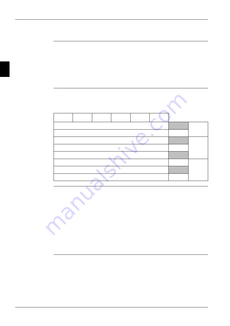
Fan staging
The fan stage shall be adjusted in steps of 1 fan.
Fan staging shall accommodate anywhere from 5 to 12 fans according to the table below:
Staging up
Six stage up dead bands shall be used. Stages one through five should use their respective dead
bands. Stages six through twelve should all use the sixth stage up dead band.
When the saturated condenser temperature is above the the active deadband, a Stage Up
error is accumulated.
Stage up Error Step = Saturated Condenser Refrigerant temperature - ( Stage Up dead band)
The Stage Up Error Step is added to Stage Up Accumulator once every 5 seconds, only if the
Saturated Condenser Refrigerant Temperature is not falling. When Stage Up Error Accumulator is
greater than 20 another stage is added.
When a stage up occurs or the saturated condenser temperature falls back within the Stage Up dead
band the Stage Up Accumulator is reset to zero.
Staging down
Five stage down dead bands shall be used. Stages two through five should use their respective dead
bands. Stages six through twelve should all use the stage six dead band.
When the saturated condenser refrigerant temperature is below the Target - the active deadband, a
Stage Down error is accumulated.
Stage Down Error Step = (Target - Stage Down dead band) - Saturated Condenser Refrigerant
temperature.
Output Number
1
2
3
4
5
6
# of fans
# of DO
*
* *
* *
5
4
* * *
*
*
*
6
* * *
* *
* *
7
5
* * *
* *
* *
*
8
*
*
* *
* *
* * *
9
*
*
* *
* *
* * *
*
10
6
*
*
* *
* *
* * *
* *
11
*
*
* *
* *
* * *
* * *
12
Содержание EWAD620-C17C-SS
Страница 2: ......
Страница 8: ...ESIE10 01 1 2 Part 1 System Outline 3 1 1 5...
Страница 111: ...ESIE10 01 General Outline Part 1 System Outline 1 105 3 1 4 5 1 36 1 Power Compressor 1 2...
Страница 112: ...General Outline ESIE10 01 1 106 Part 1 System Outline 3 1 1 4 5 1 36 2 Power Compressor 3...
Страница 113: ...ESIE10 01 General Outline Part 1 System Outline 1 107 3 1 4 5 1 36 3 Kit Pumps...
Страница 114: ...General Outline ESIE10 01 1 108 Part 1 System Outline 3 1 1 4 5 1 36 4 Circuit Fan Power Supply 1...
Страница 115: ...ESIE10 01 General Outline Part 1 System Outline 1 109 3 1 4 5 1 36 5 Circuit Fan Power Supply 1...
Страница 116: ...General Outline ESIE10 01 1 110 Part 1 System Outline 3 1 1 4 5 1 36 6 Circuit Fan Power Supply 2...
Страница 117: ...ESIE10 01 General Outline Part 1 System Outline 1 111 3 1 4 5 1 36 7 Circuit Fan Power Supply 2...
Страница 118: ...General Outline ESIE10 01 1 112 Part 1 System Outline 3 1 1 4 5 1 36 8 Circuit Fan Power Supply 3...
Страница 119: ...ESIE10 01 General Outline Part 1 System Outline 1 113 3 1 4 5 1 36 9 Circuit Fan Power Supply 3...
Страница 120: ...General Outline ESIE10 01 1 114 Part 1 System Outline 3 1 1 4 5 1 36 10 Unit Control Circuit Power Supply...
Страница 121: ...ESIE10 01 General Outline Part 1 System Outline 1 115 3 1 4 5 1 36 11 Analog Inputs Output Board...
Страница 122: ...General Outline ESIE10 01 1 116 Part 1 System Outline 3 1 1 4 5 1 36 12 Digital Inputs Board...
Страница 123: ...ESIE10 01 General Outline Part 1 System Outline 1 117 3 1 4 5 1 36 13 Digital Outputs Board...
Страница 124: ...General Outline ESIE10 01 1 118 Part 1 System Outline 3 1 1 4 5 1 36 14 Digital Outputs Board...
Страница 125: ...ESIE10 01 General Outline Part 1 System Outline 1 119 3 1 4 5 1 36 15 Extension Control Fans 1 2...
Страница 126: ...General Outline ESIE10 01 1 120 Part 1 System Outline 3 1 1 4 5 1 36 16 Extension Control Fans 3...
Страница 127: ...ESIE10 01 General Outline Part 1 System Outline 1 121 3 1 4 5 1 36 17 Extension Control Fans 4...
Страница 128: ...General Outline ESIE10 01 1 122 Part 1 System Outline 3 1 1 4 5 1 36 18 Expansion Input Output Unit Alarm Limiting...
Страница 129: ...ESIE10 01 General Outline Part 1 System Outline 1 123 3 1 4 5 1 36 19 Expansion Control Compressor 1...
Страница 130: ...General Outline ESIE10 01 1 124 Part 1 System Outline 3 1 1 4 5 1 36 20 Expansion Control Compressor 1...
Страница 131: ...ESIE10 01 General Outline Part 1 System Outline 1 125 3 1 4 5 1 36 21 EEXV Compressor 1...
Страница 132: ...General Outline ESIE10 01 1 126 Part 1 System Outline 3 1 1 4 5 1 36 22 Expansion Control Compressor 2...
Страница 133: ...ESIE10 01 General Outline Part 1 System Outline 1 127 3 1 4 5 1 36 23 Expansion Control Compressor 2...
Страница 134: ...General Outline ESIE10 01 1 128 Part 1 System Outline 3 1 1 4 5 1 36 24 EEXV Compressor 2...
Страница 135: ...ESIE10 01 General Outline Part 1 System Outline 1 129 3 1 4 5 1 36 25 Expansion Control Compressor 3...
Страница 136: ...General Outline ESIE10 01 1 130 Part 1 System Outline 3 1 1 4 5 1 36 26 Expansion Control Compressor 3...
Страница 137: ...ESIE10 01 General Outline Part 1 System Outline 1 131 3 1 4 5 1 36 27 EEXV Compressor 3...
Страница 138: ...General Outline ESIE10 01 1 132 Part 1 System Outline 3 1 1 4 5 1 36 28 Pumps Control...
Страница 139: ...ESIE10 01 General Outline Part 1 System Outline 1 133 3 1 4 5 1 36 29 Terminals M1 M2...
Страница 140: ...General Outline ESIE10 01 1 134 Part 1 System Outline 3 1 1 4 5 1 36 30 Terminals M3...
Страница 141: ...ESIE10 01 General Outline Part 1 System Outline 1 135 3 1 4 5 1 36 31 Terminals M5 MQ...
Страница 148: ...General Outline ESIE10 01 1 142 Part 1 System Outline 3 1 1 4 5...
Страница 150: ...ESIE10 01 2 2 Part 2 Functional Description 3 1 2 5...
Страница 170: ...The Digital Controller ESIE10 01 2 22 Part 2 Functional Description 3 1 2 4 5...
Страница 200: ...Functional Control ESIE10 01 2 52 Part 2 Functional Description 3 1 2 4 5...
Страница 202: ...ESIE10 01 3 2 Part 3 Troubleshooting 3 1 3 5...
Страница 254: ...Alarms and Events ESIE10 01 3 54 Part 3 Troubleshooting 3 1 3 4 5...
Страница 266: ...Controller Inputs and Outputs ESIE10 01 3 66 Part 3 Troubleshooting 3 1 3 4 5...
Страница 280: ...ESIE10 01 4 2 Part 4 Commissioning and Test Run 3 1 4 5...
Страница 286: ...Pre Test Run Checks ESIE10 01 4 8 Part 4 Commissioning and Test Run 3 1 4 5...
Страница 289: ...ESIE10 01 Running Data Part 4 Commissioning and Test Run 4 11 3 4 5 1...
Страница 290: ...Running Data ESIE10 01 4 12 Part 4 Commissioning and Test Run 3 1 4 5...
Страница 292: ...ESIE10 01 5 2 Part 5 Maintenance 3 1 5...


