


ESIE10-01
General Outline
1–95
3
1
4
5
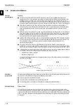
1.35
Operation
Operator's
responsibilities
It is important that the operator is appropriately trained and becomes familiar with the system before
operating the machine. In addition to reading this manual, the operator must study the microprocessor
operating manual and the wiring diagram in order to understand the start-up sequence, operation,
shut-down sequence and operation of all safety devices. During the machine's initial start-up phase,
an authorised technician is available to answer any questions and to give instructions as to the correct
operating procedures. The operator is advised to keep a record of operating data for every installed
machine. Another record should also be kept of all the periodical maintenance and servicing activities.
If the operator notes abnormal or unusual operating conditions, he is advised to consult the authorised
technical service.
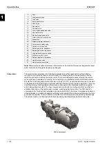
Description of the
machine
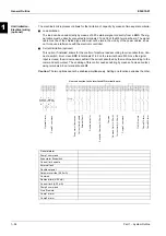
This machine, of the air-condensation type, is made up of the following main components:
Q
Compressor:
The single-screw compressor of the FR3B or FR4A series is of the semi-hermetic
type and utilises gas from the evaporator to cool the motor and allow optimal operation under any
expected load conditions. The oil-injection lubrication system does not require an oil pump as oil
flow is ensured by the pressure difference between delivery and suction. In addition to ensuring
lubrication of ball bearings, oil injection dynamically seals the screw, thus enabling the
compression process.
Q
Water exchanger:
Direct expansion, shell and tube type for all models.
Q
Air exchanger:
Finned type with pipes, internally micro-finned, directly expanded onto the
high-efficiency strip fin.
Q
Fan:
Axial, high-efficiency type. Allows for quiet system operation even during adjustment.
Q
Expansion valve:
As standard, the machine is fitted with an electronic expansion valve controlled
by an electronic control device that optimises its operation.
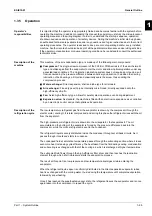
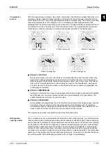
Description of the
refrigeration cycle
The low-temperature refrigerant gas from the evaporator is drawn by the compressor through the
electric motor, cooling it. It is later compressed, and during this phase the refrigerant mixes with the oil
from the separator.
The high-pressure oil-refrigerant mix is drawn into the oil separator, that separates it. The oil
accumulated on the bottom of the separator is forced by the pressure difference back into the
compressor, while the oil-free refrigerant is sent to the condenser.
The refrigerant liquid is evenly distributed inside the condenser throughout all bank circuits. As it
passes through it cools and starts to condense.
The condensed fluid at saturation temperature passes through the subcooling section where it loses
even more heat, increasing cycle efficiency. The heat taken from the fluid during cooling, condensation
and subcooling is exchanged with that of the cooling air, which is discharged at higher temperatures.
The subcooled fluid flows through the high-efficiency filter dryer and then reaches the lamination
element through which a fall in pressure starts the evaporation process.
The result at this point is a low-pressure and low-temperature liquid-gas mixture entering the
evaporator.
When the refrigerant liquid-vapour is uniformly distributed in the direct expansion evaporator tubes,
heat is exchanged with the cooling water, thus reducing the temperature until complete evaporation,
followed by superheating.
Once it has reached the superheated-vapour state, the refrigerant leaves the evaporator and is once
again taken into the compressor to repeat the cycle.
Содержание EWAD620-C17C-SS
Страница 2: ......
Страница 8: ...ESIE10 01 1 2 Part 1 System Outline 3 1 1 5...
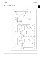
Страница 111: ...ESIE10 01 General Outline Part 1 System Outline 1 105 3 1 4 5 1 36 1 Power Compressor 1 2...
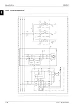
Страница 112: ...General Outline ESIE10 01 1 106 Part 1 System Outline 3 1 1 4 5 1 36 2 Power Compressor 3...
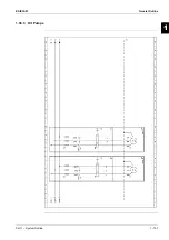
Страница 113: ...ESIE10 01 General Outline Part 1 System Outline 1 107 3 1 4 5 1 36 3 Kit Pumps...
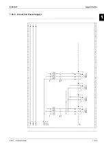
Страница 114: ...General Outline ESIE10 01 1 108 Part 1 System Outline 3 1 1 4 5 1 36 4 Circuit Fan Power Supply 1...
Страница 115: ...ESIE10 01 General Outline Part 1 System Outline 1 109 3 1 4 5 1 36 5 Circuit Fan Power Supply 1...
Страница 116: ...General Outline ESIE10 01 1 110 Part 1 System Outline 3 1 1 4 5 1 36 6 Circuit Fan Power Supply 2...
Страница 117: ...ESIE10 01 General Outline Part 1 System Outline 1 111 3 1 4 5 1 36 7 Circuit Fan Power Supply 2...
Страница 118: ...General Outline ESIE10 01 1 112 Part 1 System Outline 3 1 1 4 5 1 36 8 Circuit Fan Power Supply 3...
Страница 119: ...ESIE10 01 General Outline Part 1 System Outline 1 113 3 1 4 5 1 36 9 Circuit Fan Power Supply 3...
Страница 120: ...General Outline ESIE10 01 1 114 Part 1 System Outline 3 1 1 4 5 1 36 10 Unit Control Circuit Power Supply...
Страница 121: ...ESIE10 01 General Outline Part 1 System Outline 1 115 3 1 4 5 1 36 11 Analog Inputs Output Board...
Страница 122: ...General Outline ESIE10 01 1 116 Part 1 System Outline 3 1 1 4 5 1 36 12 Digital Inputs Board...
Страница 123: ...ESIE10 01 General Outline Part 1 System Outline 1 117 3 1 4 5 1 36 13 Digital Outputs Board...
Страница 124: ...General Outline ESIE10 01 1 118 Part 1 System Outline 3 1 1 4 5 1 36 14 Digital Outputs Board...
Страница 125: ...ESIE10 01 General Outline Part 1 System Outline 1 119 3 1 4 5 1 36 15 Extension Control Fans 1 2...
Страница 126: ...General Outline ESIE10 01 1 120 Part 1 System Outline 3 1 1 4 5 1 36 16 Extension Control Fans 3...
Страница 127: ...ESIE10 01 General Outline Part 1 System Outline 1 121 3 1 4 5 1 36 17 Extension Control Fans 4...
Страница 128: ...General Outline ESIE10 01 1 122 Part 1 System Outline 3 1 1 4 5 1 36 18 Expansion Input Output Unit Alarm Limiting...
Страница 129: ...ESIE10 01 General Outline Part 1 System Outline 1 123 3 1 4 5 1 36 19 Expansion Control Compressor 1...
Страница 130: ...General Outline ESIE10 01 1 124 Part 1 System Outline 3 1 1 4 5 1 36 20 Expansion Control Compressor 1...
Страница 131: ...ESIE10 01 General Outline Part 1 System Outline 1 125 3 1 4 5 1 36 21 EEXV Compressor 1...
Страница 132: ...General Outline ESIE10 01 1 126 Part 1 System Outline 3 1 1 4 5 1 36 22 Expansion Control Compressor 2...
Страница 133: ...ESIE10 01 General Outline Part 1 System Outline 1 127 3 1 4 5 1 36 23 Expansion Control Compressor 2...
Страница 134: ...General Outline ESIE10 01 1 128 Part 1 System Outline 3 1 1 4 5 1 36 24 EEXV Compressor 2...
Страница 135: ...ESIE10 01 General Outline Part 1 System Outline 1 129 3 1 4 5 1 36 25 Expansion Control Compressor 3...
Страница 136: ...General Outline ESIE10 01 1 130 Part 1 System Outline 3 1 1 4 5 1 36 26 Expansion Control Compressor 3...
Страница 137: ...ESIE10 01 General Outline Part 1 System Outline 1 131 3 1 4 5 1 36 27 EEXV Compressor 3...
Страница 138: ...General Outline ESIE10 01 1 132 Part 1 System Outline 3 1 1 4 5 1 36 28 Pumps Control...
Страница 139: ...ESIE10 01 General Outline Part 1 System Outline 1 133 3 1 4 5 1 36 29 Terminals M1 M2...
Страница 140: ...General Outline ESIE10 01 1 134 Part 1 System Outline 3 1 1 4 5 1 36 30 Terminals M3...
Страница 141: ...ESIE10 01 General Outline Part 1 System Outline 1 135 3 1 4 5 1 36 31 Terminals M5 MQ...
Страница 148: ...General Outline ESIE10 01 1 142 Part 1 System Outline 3 1 1 4 5...
Страница 150: ...ESIE10 01 2 2 Part 2 Functional Description 3 1 2 5...
Страница 170: ...The Digital Controller ESIE10 01 2 22 Part 2 Functional Description 3 1 2 4 5...
Страница 200: ...Functional Control ESIE10 01 2 52 Part 2 Functional Description 3 1 2 4 5...
Страница 202: ...ESIE10 01 3 2 Part 3 Troubleshooting 3 1 3 5...
Страница 254: ...Alarms and Events ESIE10 01 3 54 Part 3 Troubleshooting 3 1 3 4 5...
Страница 266: ...Controller Inputs and Outputs ESIE10 01 3 66 Part 3 Troubleshooting 3 1 3 4 5...
Страница 280: ...ESIE10 01 4 2 Part 4 Commissioning and Test Run 3 1 4 5...
Страница 286: ...Pre Test Run Checks ESIE10 01 4 8 Part 4 Commissioning and Test Run 3 1 4 5...
Страница 289: ...ESIE10 01 Running Data Part 4 Commissioning and Test Run 4 11 3 4 5 1...
Страница 290: ...Running Data ESIE10 01 4 12 Part 4 Commissioning and Test Run 3 1 4 5...
Страница 292: ...ESIE10 01 5 2 Part 5 Maintenance 3 1 5...


