Wiring Layout
ESIE11-02
1–68
3
11
4
5
3.2
Main Functions of the EUWA*5-24KBZW1 and EUWY*5-24KBZW1
Main functions
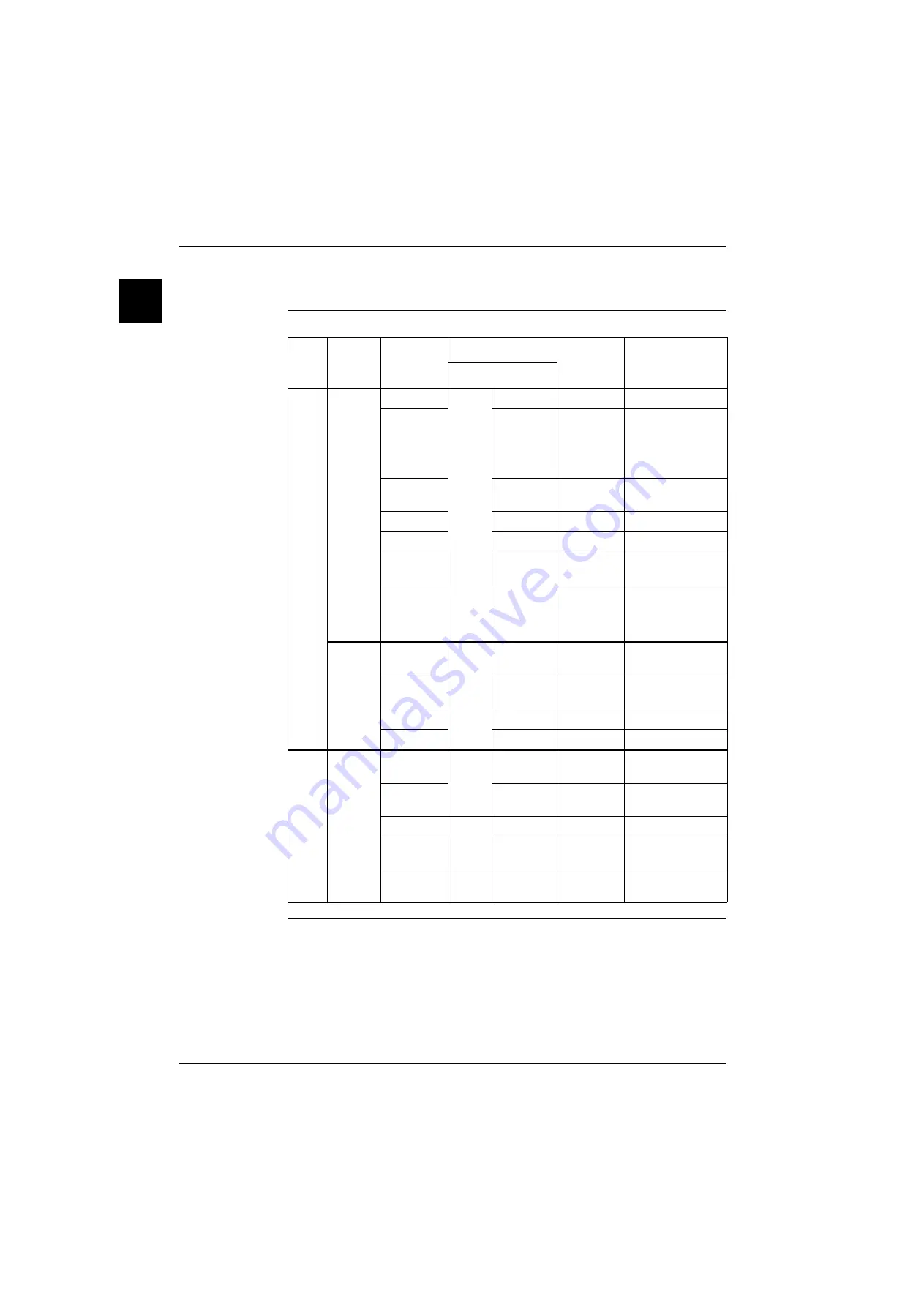
The table below describes the components connected to the µC2SE.
Ter-
minal
Signal
Connection
Wiring diagram symbol
Description
Connector I/O PCB
X1
Digital
input
ID1-GND
X71A
(5-10)
X65A
S10L
Flow switch
ID2-GND
X3M
S7S
Remote cool/heat
(only for EUWY)
or
Remote dual set-
point
ID3-GND
X6A/X7A
S1HP/S1HP
High-pressure
switch
X8A/X9A
Q1D/Q2D
Discharge protector
X10A/X11A
K4S/K55
Thermal overcurrent
ID4-GND
X63A/X64A
S4LP/S5LP
Low-pressure
switch
ID5-GND
X3M
S9S
Remote ON/OFF
or
Remote dual set-
point
Analog
input
B1-GND
X71A
(1-4)
X60A
R3T
Evaporator inlet
water t°
B2-GND
X61A
R4T
Evaporator outlet
water t°
B3-GND
_
_
_
Y1-GND
_
_
_
X2
Digital
output
C1/2-NO1
X50A
X17A
K1M
Compressor on
circuit 1
C1/2-NO2
X19A
K2M
Compressor on
circuit 2
C3/4-NO3
X51A
X29A
K1P
Contact for pump
C3/4-NO4
X5-X6/
X7-X8
Y1R/Y2R
Reversing valve
C5-NO5
X70A
X1M (1-2)
H3P
Alarm voltage-free
contact
Содержание EUWY 24KBZW1 Series
Страница 2: ......
Страница 8: ...ESIE11 02 vi Table of Contents 3 1 4 5...
Страница 10: ...Introduction ESIE11 02 viii 3 1 4 5...
Страница 12: ...ESIE11 02 1 2 Part 1 System Outline 3 1 1 5...
Страница 86: ...Wiring Layout ESIE11 02 1 76 Part 1 System Outline...
Страница 88: ...ESIE11 02 2 2 Part 2 Functional Description 3 1 2 5...
Страница 128: ...The Digital Controller ESIE11 02 2 42 Part 2 Functional Description 3 1 2 4 5...
Страница 130: ...ESIE11 02 3 2 Part 3 Troubleshooting 3 1 3 5...
Страница 168: ...ESIE11 02 4 2 Part 4 Commissioning and Test Run 3 1 4 5...
Страница 198: ...Test Run and Operation Data ESIE11 02 4 32 Part 4 Commissioning and Test Run 3 1 4 5...
Страница 200: ...ESIE11 02 5 2 Part 5 Maintenance 3 1 5...
Страница 210: ...ESIE11 02 4 Index 3 1 4 5...


